Tachometer Insallation Help

Basszilla4

Seaman Apprentice
Joined
Jun 5, 2008
Messages
44
Just installed a Faria 12 pole tachometer. F_R had kindly given me some quick instructions on installing in a different post. This is how I hooked up:

1 - Found gray signal wire in the control unit.
2 - Found purple key switch wire also in control unit.
3 - Tach has four wires on back. Red, Black, Gray, and Blue.
4 - Hooked red wire to purple wire in control. Key switch.
5 - Hooked tach gray wire to gray signal/pulse wire in control.
6 - Hooked blue wire to 12v hot on light for speedo.
7 - Hooked black tach wire to negative wire from speedo light.

All lights (speedo, tach, and fuel gauge) are hooked in sequence through a fused toggle switch. All lights work. Also, tach needle was below the "0" on the dial. Once I turned key to the on position, the needle went to the "0" position. Every time I turn key to "ON" position, the tach needle moves slightly to the "0" mark. I put my muffs on after installing and nothing. Needle doesn't move at all with engine rpm's. Tried flipping instrument light toggle switch and still nothing.

Something I am doing wrong here? Is there a way to make sure I have the "signal" going to the gray wire in control? I followed gray wire back to engine. Once it goes to big red disconnect plug on engine, I loose track of it.

My thinking is it may be how I have the ground connected on the tach itself. Just want to see if anybody has any suggestions before I start rewiring.

Any info would be greatly appreciated. Thank you.
Sincerely,
Errol (Basszilla4)
 

Basszilla4

Seaman Apprentice
Joined
Jun 5, 2008
Messages
44
Re: Tachometer Insallation Help

Anybody? Any wild guess would be appreciated... Anything... Thanks again.
 

Randyg123

Petty Officer 1st Class
Joined
Apr 20, 2008
Messages
337
Re: Tachometer Insallation Help

Have you confirmed your rectifier working?

Year and model of motor?
 

Basszilla4

Seaman Apprentice
Joined
Jun 5, 2008
Messages
44
Re: Tachometer Insallation Help

1973 Johnson 65hp 3 cylinder.

How do you check the rectifier? I have a volt/ohm meter. Would need to know what setting it would need to be on. No electrician here...lol Was going out to sample other ground sources. F_R had said to ground to the control box. This is the only thing I didn't do. Used ground from speedo light. My thinking was, a ground is a ground. Didn't think it would matter were I got the ground. Thank you for helping.
 

jtexas

Fleet Admiral
Joined
Oct 13, 2003
Messages
8,646
Re: Tachometer Insallation Help

measure the voltage on the gray (tach sender) wire with the engine running. you need at least 4 volts AC. multimeter set to "VAC", one probe on the gray wire, other probe on any good ground.

the gray wire should be hooked up to a yellow or gray/yellow wire on the engine wiring harness that eventually reaches the rectifier. probably via a terminal strip but it varies by model.

compare battery voltage with engine running, and engine not running - if it's not higher with the engine running, something's up with the rectifier. multimeter set to VDC, on probe on each battery post. If you put the red probe on negative, the reading will show negative, in which case the voltage should be more negative with the engine running.

sorry if I confused ya with that last bit, just put the red probe on positive and all will be well.

tach zeroing out with key on indicates the ground is just fine.
 

Basszilla4

Seaman Apprentice
Joined
Jun 5, 2008
Messages
44
Re: Tachometer Insallation Help

Cool. Going out and testing gray wire for AC voltage and battery voltage running/not running. Will post results in a few. Thanks a million.
 

Basszilla4

Seaman Apprentice
Joined
Jun 5, 2008
Messages
44
Re: Tachometer Insallation Help

Ok, results are in. Sorry so late, friend stopped over as soon as I went out to check. Slowed me way down and didn't want to be rude. So, as I was saying. Checked voltage at gray tachometer signal wire and battery voltage with engine running/not running. Results are:

Set voltage meter to VAC, started engine, probed tachometer signal wire and meter read 1.3 to 1.8. Was very jumpy. Hard to get a single reading at idle.

Set voltage meter to VDC and held red probe on battery positive terminal, and black probe on negative terminal. Voltage read 12.4 with engine not running. Started engine and meter read 12.3 for a second or two then went back to 12.4. Basically no change.

Now, my next question. What is a rectifier, whats it look like, where is it located on engine, where do I buy one, and whats the cost, roughly? Or could it be the alternator? Is there a way to check to make sure it is the rectifier and not the alternator? Or are we sure it would be the rectifier? Again, engine is a 1973 Johnson 65hp 3 cylinder.

Thanks again for any information. Really need help on this one. Very much appreciated.

Sincerely,
Errol (Basszilla4)
 

Reggie08

Petty Officer 1st Class
Joined
Mar 31, 2008
Messages
243
Re: Tachometer Insallation Help

Online Parts Catalog

Basszilla,
Check out the online parts diagram. Click on the link, choose year, size motor and model. On one particual model, number 64 was the rectifier. It'll give you an idea at least where it's at and what it looks like.
 

Basszilla4

Seaman Apprentice
Joined
Jun 5, 2008
Messages
44
Re: Tachometer Insallation Help

Hey thanks reggie08.

As soon as I read your post, I went looking for the part. Once I seen what it looks like, I ran outside and looked over engine till I found rectifier. The part number on mine is 510885. At least this is the only number I could read on it. Upon searching here on iboats.com, I couldn't find one that replaces this part number. All numbers start with 58????. Searched eBay and seen a bunch of new ones in the 25 - 30 dollar range that claim to fit the 1971 - 1973 65hp Johnson. 6 - 10 amp, 3 wire. Sure hope this is whats causing tachometer not to work and battery not to charge. Although, engine always starts in a half second and with brand new deep cycle battery, never knew it wasn't charging.

Now, what are the chances it could be the alternator? I hate buying parts I don't need. Is there a way to test alternator for volt/amp output to make completely sure before I commit to buy the rectifier? Although, for 30 bucks, and the way mine looks, I will buy rectifier regardless. Would just want to make sure alternator is in good condition in case I would need to buy something for that.

Thanks again for any information. I really appreciate everybody's help.

Sincerely,
Errol (Basszilla4)
 

Basszilla4

Seaman Apprentice
Joined
Jun 5, 2008
Messages
44
Re: Tachometer Insallation Help

Sorry reggie08,

At first, I didn't see the link in your post. I searched iboats for Johnson/Evinrude parts. Then seen your link. Either way, wonder is there a way to test alternators volt/amp output? Thanks again...

Errol (Basszilla4)
 

Reggie08

Petty Officer 1st Class
Joined
Mar 31, 2008
Messages
243
Re: Tachometer Insallation Help

I don't know much about your motor but I just installed a Faria 6000rpm tach myself and was told by ezeke to set it at 4. Did that and it's working perfectly! You might check the setting just to be sure.

But check out this post by J.Reeves. Might be of use

Small Rectifier Test
 

Basszilla4

Seaman Apprentice
Joined
Jun 5, 2008
Messages
44
Re: Tachometer Insallation Help

Hmmmm, very interesting post there reggie08. I will definitely try that test tomorrow. Will post any abnormal results. My Faria tachometer has no selector switch on back. Nothing to "set". Only has a sticker that says, "For 12 Pole Only". Doing research I found my engine to be a 12 pole alternator. Was told it would work. Thanks again.
 

Randyg123

Petty Officer 1st Class
Joined
Apr 20, 2008
Messages
337
Re: Tachometer Insallation Help

You didn't mention at what rpm you tested the rectifier's voltage output. I know with mine, I need to have the rpm's above idle to see much, if any, difference.
You should be getting a higher voltage (13+) coming from your rectifier when the rpms are above idle (say around 1200rpm).


To test your rectifier

The rectifier is a set of four diodes that convert A/C voltage to D/C voltage in order to charge your battery. Diodes pass voltage only in one direction so you can use a multimeter to check if each diode is good or bad. Many newer multimeters have a "diode check" setting. If no diode setting then you must use a resistance setting.

Before working on the rectifier, disconnect your battery!

Remove all the leads on the rectifier.
Set the meter to diode test and put the meter's red test lead on the red wire of the rectifier. With the black test lead touch the yellow wire. Then reverse your meter leads with the black lead on the red wire and the red lead on the yellow wire.
In one direction you meter should display 'OL' or whatever your meter uses to indicate an open circuit or high resistance. In the other direction you'll get a number (not important what you get, just that it doesn't say 'OL').

Repeat this procedure with the red and yellow/gray wire combination.

Then do the same thing with your rectifier's black wire performing the diode test on the black to yellow and the black to yellow/gray combinations.

So now you have tested four wire combinations in two directions each, to see if they will or will not pass a voltage.

Red-Yellow
Yellow-Red

Red-Yellow/Gray
Yellow/Gray-Red

Black-Yellow
Yellow-Black

Black-Yellow/Gray
Yellow/Gray-Black

For each of the above combinations you should get a number in one direction and an 'OL' in the other direction. Anything different, and you have a problem. If you get voltage going both directions across a diode; or if you get an open circuit in both directions across a diode; the rectifier is toast.

There are a lot of posts covering this subject. Some get into really good detail on what is going on and exactly what readings you should see. I hope this generic info will help you. I just went through my rectifier and found that only one diode was passing voltage. That made my tach display only 50% of the actual rpm.
Good luck
 

jtexas

Fleet Admiral
Joined
Oct 13, 2003
Messages
8,646
Re: Tachometer Insallation Help

The "alternator" on your motor consists of the following:
Coils of copper wire on the stator,
A couple magnets glued to the underside of the flywheel, and
The rectifier.
 

Basszilla4

Seaman Apprentice
Joined
Jun 5, 2008
Messages
44
Re: Tachometer Insallation Help

You didn't mention at what rpm you tested the rectifier's voltage output. I know with mine, I need to have the rpm's above idle to see much, if any, difference.
You should be getting a higher voltage (13+) coming from your rectifier when the rpms are above idle (say around 1200rpm).

Hey, thanks for the reply Randyg.

When I was testing voltage to the battery, I had first tested without engine running. Then had a buddy start engine while I held probes on battery terminals. As engine starts, it tends to rev up on its own for a few seconds before calming back down to normal idle. The meter probes were on the entire time this happened. As buddy started, engine revved up, then back down. Being I have never had a tachometer installed, I can only guess at the rpm's as engine starts. My guess is it revs up to well over 1200, before calming back down to normal idle rpm. Either way, there was absolutely no change in voltage output. Going out to test the ohms of the rectifier. Will post any and all results.

Thanks again for the help...
 

Basszilla4

Seaman Apprentice
Joined
Jun 5, 2008
Messages
44
Re: Tachometer Insallation Help

The "alternator" on your motor consists of the following:
Coils of copper wire on the stator,
A couple magnets glued to the underside of the flywheel, and
The rectifier.

Thanks jtexas.

So, the "Alternator" isn't the same as on say, a car. No armature or brushes to wear out. More like a magneto? This being true, there shouldn't be anything to "wear out" on the alternator. Besides the rectifier. Will be checking that here in a few.

Thanks again
 

Randyg123

Petty Officer 1st Class
Joined
Apr 20, 2008
Messages
337
Re: Tachometer Insallation Help

Hopefully someone can jump in and let you know what your coil resistance (and other test parameters) should be for that model engine and you can check those to see if they are good. I don't have any of that info. But you might as well confirm that those parts are working. The rectifier just converts the A/C to D/C; so if the A/C signal is bad, replacing the rectifier won't fix that.

From what I have read on this site, the most common reason for rectifiers going bad are hooking up the battery backwards (or jumper cables). That's an instant bye-bye rectifier situation.

Do you have a service manual? A lot of this information can be found in that. If you don't have an OEM manual look at the top of the forum page; there's a link to where you can buy them:D
 

Basszilla4

Seaman Apprentice
Joined
Jun 5, 2008
Messages
44
Re: Tachometer Insallation Help

Thanks again Randyg.

Well I went and tested the rectifier and all is not good. Set volt meter to ohms, placed black probe on rectifier base and touched red probe to all three wires. Nothing. Then swapped red and black probes and tried again. Same thing, nothing. Then put red probe on red wire and touched other wires. Nope. Reversed probes and same thing. Nothing. Touched the two probes together just to make sure it wasn't my volt/ohm meter acting up. When touched, display went to "0". No matter which way I touched any wires together, I got nothing. No change on ohm meter whatsoever.

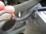
So, I took off the rectifier and saw something that might give a sign as to why this rectifier isn't working. See photo below. Safe to say this one is fried?

As for a manual, my brother-in-law just informed me he has a service manual on a couple CD's for Johnson Outboards from 1960's to 1990's. Might be a week before I receive it though. Who can wait that long when there is all these smart boating guru's here on iboats.com...lol Just ordered a new rectifier and hopefully will be here in a few days.

Thanks again for any info...
 

Attachments

  • IMG_0012 Resized 3.jpg
    IMG_0012 Resized 3.jpg
    90.4 KB · Views: 0

Randyg123

Petty Officer 1st Class
Joined
Apr 20, 2008
Messages
337
Re: Tachometer Insallation Help

If you multimeter doesn't have a 'diode check' feature and you are forced to use the resistance feature to check a diode you must be careful interpreting the results. Since you got infinite on all tests that would indicate that all diodes are open. Some multimeters, the resistance feature may not truly indicate a diode's function due to the electronics of the meter. But in your case the battery isn't charging and your tach isn't working correctly. I'd say if it looks like a duck, walks like a duck, and quacks likes a duck, you've got a duck.

Melted wires is just just another clue.

But then, what caused that?

You need to ask someone to post instructions on how to test your particular charging system to make sure your coil is working. As for the CD manual, it better be an OEM. Otherwise you may end up misinformed.
 

Basszilla4

Seaman Apprentice
Joined
Jun 5, 2008
Messages
44
Re: Tachometer Insallation Help

Melted wires is just just another clue.

But then, what caused that?

Don't think that wire was melted. Could be, but looks more like dry rot and cracked/corroded. Don't know about manual. He is sending them CD's to me through the mail. Will be a few days before I get them. I think he said they were OEM. I'll have to wait and see. If not OEM, I am going to just buy a service manual for this engine. Better to have one and never need it, than need one and not have it... Like me right now...lol

Just threw out another post named, "Anybody know what this is?". Maybe you could check it out and see what I am talking about. Uploaded pictures. I have no clue...

Thanks again...
 
Top