diode installation

$20boat

Cadet
Joined
Oct 1, 2009
Messages
16
The diode in my fuel pump circuit has gone bad. i noticed that it was crimped in place with copper or brass coupling. it was also sealed with silicon.

Can anyone provide me with the correct procedure for installing a new diode?

thanks!
 

bruceb58

Supreme Mariner
Joined
Mar 5, 2006
Messages
30,581
Re: diode installation

First off, how do you know your diode is bad? How did you test it?

Second, a diode has an anode side and a cathode side with the current flowing through the diode from the anode to the cathode. A diode is marked with a stripe on one end. That side is the cathode and should be the side facing the fuel pump relay.

diode.gif
 

$20boat

Cadet
Joined
Oct 1, 2009
Messages
16
Re: diode installation

before i removed it i checked it with a ohm meter, and i checked it both directions just to be sure. read infinity one way, 900 ohms the other. After i removed the silicone cover, i checked it again, it now read infinite in both directions ( probably finished the failure of it!). after removing it, i checked it adn it was still infinite both ways( just to be sure!)

i did note the direction of installation, as you noted, it's a one way device.

Best i recall, you don't solder diodes without a heat sink. So, do you have a standard procedure for installing a new one and sealing it? This one had about 3/4" on each end, seems that might allow the fatigue of the wire during vibration; what do you think?

thanks
 

bruceb58

Supreme Mariner
Joined
Mar 5, 2006
Messages
30,581
Re: diode installation

If you measured it with an ohm meter, you didn't test it corectly. The reason is that most ohm meters check with voltages lower than the turn on voltage so the diode will never conduct. Many meters have diode tester settings and it will show you the forward voltage that the diode turns on at. Typically this is 0.7V.

If you really want to see if the diode is the problem, take the wire off the alternator, connect that wire to 12V and see if you fuelpump turns on. If it doesn't, then jumper the diode with the wire still hooked up to 12V. If it turns on, then its your diode, if not, there is a problem with the fuelpump relay.

There is no problem soldering a diode. It is crimped into the factory wiring harness because wiring harnesses are really not supposed to ever be soldered.
 

$20boat

Cadet
Joined
Oct 1, 2009
Messages
16
Re: diode installation

the voltage reading on the starter relay line that feeds the fuel pump (FP) relay was 12.7 V at the starter relay. the line coming into the FP relay end of the wire read 7.8V, after going thru the diode. a resistance reading on the line from the Starter terminal to just before the diode read 0 ohm (before uncovering the diode).
 

Alpheus

Lieutenant Commander
Joined
Aug 3, 2009
Messages
1,759
Re: diode installation

Just put a new diode in. They dont cost much. Also my Fluke can test a P/N junction in the OHM function...
 

bruceb58

Supreme Mariner
Joined
Mar 5, 2006
Messages
30,581
Re: diode installation

the voltage reading on the starter relay line that feeds the fuel pump (FP) relay was 12.7 V at the starter relay. the line coming into the FP relay end of the wire read 7.8V, after going thru the diode. a resistance reading on the line from the Starter terminal to just before the diode read 0 ohm (before uncovering the diode).
This is the diode coming from the alternator right. There are two diodes...one from the starter and one from the alternator.

If this is the one from the alternatior did you measure this with the engine running? What was the voltage at the output of the L2 terminal of the alternator? I would be willing to bet its not the diode.

When you measured 900 ohms did you have the wire going to the alternator disconected and the fuel pump relay out of its socket?
 

bruceb58

Supreme Mariner
Joined
Mar 5, 2006
Messages
30,581
Re: diode installation

Just put a new diode in. They dont cost much. Also my Fluke can test a P/N junction in the OHM function...
My Fluke can't. What model and what range do you use? If your Fluke is a digital meter it can't make that measurement in the ohms setting...only diode test.

I just tried it now just to verify. You can't measure a diode with ohm settings on my Fluke 77.
 

Glastron_V210

Petty Officer 1st Class
Joined
Jan 28, 2009
Messages
324
Re: diode installation

The worst, diodes (LEDs) take about 1.5V in the forward direction to conduct. Most general purpose, fast, ultra fast etc are around .55-.7V. Shottkeys are around .2-.3V.

I have a hard time believing the Fluke doesn't make 1.5 V on the ohms scale. All mine certainly do (87,187,167,177).

The difference between the ohms and diode test is this:

The diode mode is a 'constant current' mode. The meter tries to push a current (1ma I think) and then displays the voltage required to flow the current. So, you will see a .567V on the display for a regular diode like a 1N4001 or similar general rec. diode.


Ohms mode outputs a voltage and measures the current and does a simple calculation to create an ohms value. Because the current is not limited in many meters, it can exceed the capacity of many small diodes (500ma and under) and cause damage to them. It is not recommended to use ohms for this reason. Most diodes will do fine if you are just checking for 'diode action'. 900 ohms seems really high though, usually you get a value under 1 ohm, so I suspect you are right about your diode being 'open circuit', or what I like to call 'toast'.

C
 

Glastron_V210

Petty Officer 1st Class
Joined
Jan 28, 2009
Messages
324
Re: diode installation

As far as hooking up your new diode....There are bunch of ways to make it mechanicaly sound.

You can solder it, no problem. In a normal situation I'd suggest mounting it on a board, or with 2 terminal blocks but that doesn't sound like it will work here.

If there is a way to do it, you can use 2 part epoxy which is a good dielectric material (Its used to repair circuit boards a fair bit) and glue it down to something solid (Insualted and solid) if there is one near. That will reduce any vibration fatigue. I like to heat shrink the leads/wires, and then have a heat shrink over the whole thing.

Does the diode look like a block (With a screw mount for heat sink) or is it just a 2 lead device like the picture in BruceB58's post? If it's a 2 lead device I'd want it stuck onto something solid.

C
 

EricKit

Petty Officer 3rd Class
Joined
Aug 31, 2009
Messages
81
Re: diode installation

Hello, I figured I'd give a little insight into how a diode works so you can know if you are measuring it correctly.

To measure a diode use the diode setting on a digital multimeter.

For an analog multimeter, use a low value resistance setting and measure it to get the highest voltage across the diode. Also on analog multimeters the positive and negative ends are reversed on resistance readings for how the meter works (Black to anode, Red to cathode to test it working).

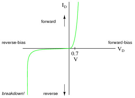
A diode has a 0.7 Volt drop across it in any circuit at almost any positive current draw. This is much different than a resistor where the voltage is directly proportional to current draw. Without a 0.7 volt difference across the diode, very little current will flow (Which will give you wrong readings). After the diode, the wire will be 0.7 volts lower. You can see the picture below to demonstrate, however, that the voltage drop does vary slightly with current. This picture also shows that below 0.7 volts, some current will flow.

03253.png


So unless your multimeter is providing > 0.7 Volts (assuming silicon diode), then it will not read properly on the resistance setting. Well technically it will never read correctly, but it will give a low resistance with enough voltage.

Also, if the voltage is very high, Maybe > 50 Volts in the opposite direction, current will flow in reverse, this is the breakdown voltage.

An LED diode is the same as a diode except instead of using Silicon they use other materials, such as Silicon carbide for Blue. When current flows across a diode electrons fill places where electrons should be (Called holes), which causes them to change energy levels. When this happens a photon is released. The size of the change in energy levels directly relates to the frequency of the light (or the color).
 

bruceb58

Supreme Mariner
Joined
Mar 5, 2006
Messages
30,581
Re: diode installation

I suspect the OP measured the diode while in the circuit to get the 900 ohms.

Glastron, have you ever tried to measure a diode with the ohms setting on a meter? Also, digital meters do not put out large amount of currents in the ohm setting.
 

Glastron_V210

Petty Officer 1st Class
Joined
Jan 28, 2009
Messages
324
Re: diode installation

Yeah, I have lots of times with no difficulty.

Ohmmeters can be fooled in two ways:

1) Voltage across the device being measure can produce unpredictable results. If the voltage is in polarity with the ohmeter, a lower value will register (Like below 0 even). With reverse polarity the resistance measurement will look to high. The reading is usually pretty flaky when this occurs.

2) Parallel current paths exist due to the presence of the circuit elements in parallel with the device being measured. This will lead to a lower resistance than is accurate.

You can accurately measure elements in circuits, even those which are powered up as long as the device under measure doesn't have parallel paths. Its like a circuit within a circuit, which is fine.

Digital meters don't put out much current period. They are usually powered by a 9V battery, or multiple AA (1.5V) in series which is not much of a source. They will put out plenty to forward bias a diode though.

C
 

Alpheus

Lieutenant Commander
Joined
Aug 3, 2009
Messages
1,759
Re: diode installation

My Fluke can't. What model and what range do you use? If your Fluke is a digital meter it can't make that measurement in the ohms setting...only diode test.

I just tried it now just to verify. You can't measure a diode with ohm settings on my Fluke 77.

Just replaced my Fluke 189 with a 289. My 189 would do it and Im positive the 289 will do it also. I dont use the Ohm function to test diodes but it does work when I was messing with it when I first got it...
 

$20boat

Cadet
Joined
Oct 1, 2009
Messages
16
Re: diode installation

Well, it was the diode. Voltage to the relay was 7.2 volts before replacing the diode and 9.3 afterward. after researching the relay specs, the relay requires 8.5v to function.

thanks for your help!
 

lowkee

Lieutenant Commander
Joined
Dec 13, 2008
Messages
1,890
Re: diode installation

Nice job on diagnosing the issue instead of simply buying a new part. Always love it when a 50 cent part repairs a high cost assembly.

I once bought a Dodge Neon at auction for way below value because their was tons of steam/smoke coming from the engine area. Come to find out, it was a tiny hole in a freeze plug.. 25 cents and 30 mins later I had a perfectly working car (still have it today).
 

bruceb58

Supreme Mariner
Joined
Mar 5, 2006
Messages
30,581
Re: diode installation

Well, it was the diode. Voltage to the relay was 7.2 volts before replacing the diode and 9.3 afterward. after researching the relay specs, the relay requires 8.5v to function.

thanks for your help!
It should be 12V(or whatever the L2 terminal puts out) minus the diode drop. You still have a problem if the voltage is that low.

What is the voltage at the L2 terminal of your alternator while the engine is running.
 
Top