Alignment Tool

Status
Not open for further replies.
Joined
Mar 30, 2009
Messages
17
I purchased an after market alignment tool so I could check my outdrive alignment each year myself. But when I went to check it this winter, it would not enter the female splined portion of the engine. Although I had the alignment checked by my mechanic last winter and it was fine, I assumed the engine needed adjusting. However, after raising the engine a bit, it still would not even start to fit. My next thought was the tool was the wrong size. I found the end portion of the tool to be 1.012" in diameter. However, the internal space between the splines on the drive shaft was only .978". This makes me believe the tool is definetly too big. The motor is a 1994 Merc 7.4 with Bravo II outdrive Does anyone know the correct measurements for this tool. I probably will have to take it to a shop and have it machined to the correct diameter. Thanks
 
Joined
Mar 30, 2009
Messages
17
Re: Alignment Tool

No, this is the first time I tried to use it. So it never has worked. I just need someone to provide the correct measurements.
 

Bondo

Moderator
Staff member
Joined
Apr 17, 2002
Messages
71,082
Re: Alignment Tool

Ayuh,... Did you click on the link Don provided,..?? Guess not...
The small ends is 1.010", just as the picture in the link states...
 
Joined
Mar 30, 2009
Messages
17
Re: Alignment Tool

Ya sorry, did not see attachment the first time. Well, your right, .002 would not be enough to probably be the problem. I have had people tell me to be sure I am moving the gimbal bearing around. But I do not see anyway that bearing moves. I just do not see how it could have gotten that far out of alignment in one season?
 

Lou C

Supreme Mariner
Joined
Nov 10, 2002
Messages
13,025
Re: Alignment Tool

The gimble bearing does 'gimble' a bit like an eyeball socket...the first time you use an alignment bar you will note that you need to move the tool around a bit after the tool goes into the gimble bearing so that it can go straight into the coupler splines...so what I am saying is that either you didn't move the tool around as needed to get the gimble straight so that the end of the tool could enter the coupler splines...or the engine really IS out of alignment....
 

havasuboatman

Ensign
Joined
Mar 5, 2009
Messages
904
Re: Alignment Tool

Your problem is you aren't using it correctly. You do have to move the gimble gearing around. It's not just a matter of moving the engine up and down. Also, .002 is too much. Bearings that have to be pressed on and off are only .004-.006 under.
 

KJSmitty

Petty Officer 2nd Class
Joined
Aug 9, 2008
Messages
179
Re: Alignment Tool

I purchased an alignment tool about a year ago and it was the first time I checked the alignment myself. The previous 3 years it was "supposedly" performed by my authorized Volvo tech/service center etc.

Needless to say when I first checked, the bar would not enter the splines either - would slide through the gimbal bearing and hit/stop... With a little finesse I was able to get it to start, then with entirely too much force, it slid into the coupler. Needless to say it was considerably out of alignment.

I truly don't think it was ever checked, even though I was billed for the drive being removed each season. My boat being only 4 years old and visually checking, the rear mounts looked fine. I came to the conclusion that it was probably off from the factory then combined with a little mount settling, resulted in the major misalignment etc..
I ended up lowering the engine (front) by 1/2 an inch for proper alignment. The bar then slid in like butter - even when rotating the crank at 90 degree intervals etc. I checked it again this fall during winterization and it had not changed over the last season etc.

Bottom line, it very well could have changed that much or could have been off all along. You also should try rotating the engine/crank at 90 degree intervals and see if your tool will slide in.
You also mentioned you "raised" the engine and had no luck. If your rear mounts did settle, raising the front would have only made the alignment worse. Try dropping it down twice what you had raised and start there.

Good luck
 

bruceb58

Supreme Mariner
Joined
Mar 5, 2006
Messages
30,581
Re: Alignment Tool

Also, .002 is too much. Bearings that have to be pressed on and off are only .004-.006 under.
Not sure what that has anything to do with this. We are talking about the dimension going into the coupler.
 

bigskiohio

Master Chief Petty Officer
Joined
May 3, 2008
Messages
882
Re: Alignment Tool

just start the tool then tap on bar in the four directions to line up gimble then you adjust the engine , if gimble is aligned teh engine mounts have a problem. Learn to this your self so you dont have to trust somebody else.
 

Northernbob

Cadet
Joined
Dec 6, 2009
Messages
27
Re: Alignment Tool

I just repalced my engine, had to fiddle for two hours to get a good alignment,
ended up 1/2 inch lower than the previous engine, leg slid on like butter.
I made a jig that went across the boat, a 4x4 drilled a hole used a piece of redi-rod with a hook and raised and lowered the engine with a large wing nut, once I found a sweet spot I proceeded to adjust the mounts, alot less crawling around the bilge.
 
Joined
Mar 30, 2009
Messages
17
Re: Alignment Tool

OK, I obviously am confused and need more help. I apparently do not fully understand how this set up works. Always had outboards all my life, so this is all new to me. I had assumed that the bearing was rigid and centered in the bell housing to keep the drive shaft aligned with the outdrive, since they bolt together. If the bearing can move around, would'nt that allow the drive shaft to exert misaligned forces on the outdrive side?? I have had the drive off since I winterized the boat in November and have tried several times to make this work. I have inserted the tool into the bearing and tried moving it without any apparent movement. I do not want to try any harder in case I am doing it wrong and could damage the bearing. I don't suppose anybody knows of a video online showing exactly how this suppose to be done?? Thanks
 

Northernbob

Cadet
Joined
Dec 6, 2009
Messages
27
Re: Alignment Tool

Quite simple.
The shaft slips thru the gimbal bearing and then on to the coupler, but your coupler is so far out it wont accept the shaft, you have to move the front of your engine up or down via the mounts (or jig)to get it close then fine tune it. It's not a five minute job. Hope this helps.
 

TFHTECH

Seaman Apprentice
Joined
Feb 1, 2010
Messages
30
Re: Alignment Tool

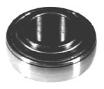
put grease on the end of your tool and slide it in the hole (god did i just say that) pull the tool out and look in the hole at the back of the coupler if you can c were the tool had left a mark on it from the tranferance of grease this should guve you so ideal of witch way you need to go. the bearing will move inside its housing and you can move it around with your tool some move easy and some you have to use some force to get it to move somtimes when you pull the drive off it moves the bearing. if you look it the alginment shaft hanging out of the boat you sould be able to tell witch way it needs to arte you get the bearing close the you can start on your mounts moving them up or down if it way off then you should c some sort of wear on the outdrive shaft and splines here is a pick of the bearing out of the boat and it tolerance ring1) here is a step by step on how to align


Start with outdrive DOWN , and shift in forward gear.

2)Step on left side blade and force downward (CCW).

3)Watch the engine pulleys when the prop turns.

4)If the engine turns, the coupler is usually good.

5)If the engine does not turn when the prop turns something is broken.

6)If propshaft does not turn with prop, the prop clutch is stripped..

7)If the shaft behind the engine doesn?t turn but the propshaft does your outdrive is broken.

8)If the prop and shaft turn and the shaft behind the motor, but not the engine, your coupler is broken.

9)Before replacement of the coupler, check the following.

10)Look across the boat transom and have a heavy person stand on outdrive and bounce.

11)If the transom flexes it will cause failure and must be repaired before the coupler is changed.

12)If the front motor mount is loose or if the pad where it sits is rotten, alignment will cause failure.

13)If these mounts and transom are good proceed with coupler change.

14)There are several possible couplers most are available aftermarket.

15)The im850 fits all Chevrolet with 3-1/2" bolt pattern on crankshaft.

16)The im598 fits all v-8 Fords.

17)Newer Chevrolet take the triangle coupler (small for 12-1/2 f/w large for 14" f/w).

18)If you do not know the size of the f/w, measure across two holes (10" or 11").

19)The im505 fits newer v-8 Chevrolet engines with 3" bolt pattern to avoid the triangle coupler.

20)The 224 C.I.D. Mercruiser uses two different couplers which are the early coupler or the late model coupler thru aftermarket.

21)When coupler is removed the reason for failure can be determined.

22)There are five possible failures.

23)Rubber in coupler broken in half (Struck under water object).

24)Splines internal in the coupler gone (lack of lube on splines long term) or bad rear height alignment (short term)

25)Rubber slipping in external shell (underwater object if old, possible flaw if new)

26)Rubber separated from core spline (hit underwater object if old) possible flaw if new.

27)Rubber melted (most common) poor alignment.

28)Only reason 25 or 26 have any chance for warranty and then only if part is new.

29)If melted and transom and mounts are good, Check alignment.

30)Alignment is the correct angle of the engine so the rubber in the coupler does not have to bend when the shaft from the engine is inserted through the gimbal bearing.< The rubber is suppused to turn the shaft but stay undisturbed when the shaft is inside. It is always easy to hit the rear opening of the coupler with the outdrive shaft, but the shaft mist go directly thru from there. Any slight elevation or drop in the front of the engine will cause the rubber insert to flex to allow the shaft inside. when the engine turns 1/2 turn the rubber flexes the opposite way. This flexing at 4000 rpm causes the rubber to heat untui it melts.

After the engine coupler is installed and the engine replaced the rear mount bolts are important for rear allignment. The metal washer goes on the bolt followed by the spacer. These three pieces go thru the engine mount from the top. In the space between the engine and the transom plate support tabs there should be two washers one fiber and one lockwasher which fit inside eachother with the bolt from above going thru into the hole in the tab. The nut goes on the bottom of the tab. This bolt must be tight before the allignment is checked.

Push an allignment bar through the gimbal bearing and into the engine coupler, tapping it to full depth. Hit the rear of the bar on the top and side with a large hammer to allign the bearing with shaft. Take the shaft and try to pull the bar in and out of the coupler with thumb and forfinger. If this is possible the allignment is correct. If the bar is hard to move in and out the allignment is out. Hang the motor front lifting ring on a hoist or come-along and loosten the front mount so the motor can fall further down than it started then have someone lift and lower the front of the engine until the bar slides easily, at this point lower the mount to support the engine at this height. Remove the hoist and recheck the bar. Fine tune the allignment by turning the mount nut for least resistance on the allignment bar. Good luck
 

Attachments

  • gimble no ring.jpg
    gimble no ring.jpg
    9.4 KB · Views: 0

achris

More fish than mountain goat
Joined
May 19, 2004
Messages
27,468
Re: Alignment Tool

If it's so far out of adjustment that you can't get the tool in, then you need to get it closer (to adjustment).

Just get a small torch (flashlight for you yanks :D) and look in and see the coupler... Adjust the engine up or down so it looks close to alignment... That is your starting point... You can get it pretty close visually...


Chris........
 

Don S

Honorary Moderator Emeritus
Joined
Aug 31, 2004
Messages
62,321
Re: Alignment Tool

Nice copy and paste TFH, (obviously not yours) where did you get it from, because I have some exceptions to the technique you posted.
 

TFHTECH

Seaman Apprentice
Joined
Feb 1, 2010
Messages
30
Re: Alignment Tool

im shur you do, its from an old book that i had. just trying to help
 

bruceb58

Supreme Mariner
Joined
Mar 5, 2006
Messages
30,581
Re: Alignment Tool

Here is my alignment instructions. Of course the OP has to get past step 1.

Inspect the splines on the shaft for visible wear, generally if the splines
are worn then the coupler is also worn. If wear is evident replace the parts
as needed.


NEVER Force the alignment tool in, you can damage the tool and the coupler.

NOTE: If you find the tool will not slide into the gimbal simply remove the
black coating on the largest step with fine sand paper.


1) Once you have the engine height close enough to
fully insert the tool without force, then you can start
working on setting the proper alignment.

Take your time, getting it close enough to insert the
tool the first time can sometimes be the hardest (most
frustrating) part.

2) Coat the end section of the tool (the smallest diameter
area) with a light coat of grease and then insert it fully
into the coupler.

3) Without turning the tool, pull it straight out and look at
the depth of the teeth marks in the grease.

If the teeth marks in the grease are deep on the
top side and shallow on the bottom side of the tool then
your motor is too high.

If the marks in the grease are deeper on the bottom than
on the top then your motor is too low.

4) Adjust the engine height accordingly.

5) Keep checking the depth of the marks in the grease until
they are equal in depth on top and bottom.

Sometimes as little as 1/8th of a turn on the adjusting nut can be the
difference between being properly aligned, and just having it "close"

Lightly Grease the splines on the shaft (and on the coupler if you can) with
Spline grease prior to assembly.
 

achris

More fish than mountain goat
Joined
May 19, 2004
Messages
27,468
Re: Alignment Tool

...

1) Once you have the engine height close enough to
fully insert the tool without force, then you can start
working on setting the proper alignment.


....

And that's where the problem is.... No point in giving him a long list of instructions when he can't even get the tool in yet!

Chris....
 

bruceb58

Supreme Mariner
Joined
Mar 5, 2006
Messages
30,581
Re: Alignment Tool

He will need them eventually. Shouldn't be too hard to get the engine close assuming his rear engine mounts are still in good shape and nothing catastrophic has happened with his stringers.
 
Status
Not open for further replies.
Top