Hello
I have recently picked up a 97 Bayliner with 4.3 V-6 Engine ..Im trying to figure out some wireing nightmaress here..there was a lot of splicing and what not going on the engine wireing harness ... Engine has Electronic Ignition with thunderbolt IV module on the back of the distributor ....Here is what im haveing problems with....
Oil pressure cutoff switch connection ..since there is no ecm in the boat i dont undersatnd how it is suppuse to work ..looking at the manual wire from the oil pressure cuttof switch runs to the electric fuel pump...but it wont since there is no pressure when the engine is not running ....so what should i do about the switch just take it out? Im not sure if the boat had a different setup before or not but it is carburated now has electric fuel pump and electronic ignition...
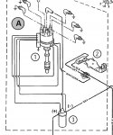
The other problem is Shift cutout switch .....has two connections one ground and the other one according to the manual should go to one of the wires comming out form the distributor (white/green) and white/ green is already connected to the module on the back of the distributor along with white/red...Do i splice in to the white/green comming from the distributor or am i missing somethiing here
Any help would be really appreciated !!!
I have recently picked up a 97 Bayliner with 4.3 V-6 Engine ..Im trying to figure out some wireing nightmaress here..there was a lot of splicing and what not going on the engine wireing harness ... Engine has Electronic Ignition with thunderbolt IV module on the back of the distributor ....Here is what im haveing problems with....
Oil pressure cutoff switch connection ..since there is no ecm in the boat i dont undersatnd how it is suppuse to work ..looking at the manual wire from the oil pressure cuttof switch runs to the electric fuel pump...but it wont since there is no pressure when the engine is not running ....so what should i do about the switch just take it out? Im not sure if the boat had a different setup before or not but it is carburated now has electric fuel pump and electronic ignition...
The other problem is Shift cutout switch .....has two connections one ground and the other one according to the manual should go to one of the wires comming out form the distributor (white/green) and white/ green is already connected to the module on the back of the distributor along with white/red...Do i splice in to the white/green comming from the distributor or am i missing somethiing here
Any help would be really appreciated !!!