1967 johnson V4TL-13A pulsepack wiring diagram/info

turbofn1

Recruit
Joined
May 5, 2011
Messages
5
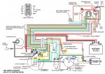
I have a 1967 johnson meteror V4TL-13A 100hp that MARINEENGINE.COM parts shows to have a CDI IGNITION installed, it was converted to battery points system that I am looking to return to CDI. The wires from the harness the best I can tell are 2 red wires one to voltage reg, and one to coil, and a white or yellow wire to voltage reg, then another harness with a blue wire, white with red stripe wire, and a yellow wire, would appreciate any help, this motor appears to be first style with CDI system setup, if anyone has a wiring diagrahm or any helpful info it would really help, I was able to get almost all the parts needed except for the sensor plate and pin assy 580670, cable assy 382399 and the pulse pack 381884 which all seem still available but just waiting on funds, Thanks for any help !!
 

F_R

Supreme Mariner
Joined
Jul 7, 2006
Messages
28,226
Re: 1967 johnson V4TL-13A pulsepack wiring diagram/info

Here ya go---
 

Attachments

  • Wiring 1967 100S Verified fr.jpg
    Wiring 1967 100S Verified fr.jpg
    139.6 KB · Views: 16

boobie

Supreme Mariner
Joined
Nov 5, 2009
Messages
20,826
Re: 1967 johnson V4TL-13A pulsepack wiring diagram/info

Leave it with the battery ignition system on it. Less costly to maintain and less trouble over all. That was one of the worst battery cd ignition systems OMC everbuilt. Why do you think it was converted to the ignition it has on it now ??
 

turbofn1

Recruit
Joined
May 5, 2011
Messages
5
Re: 1967 johnson V4TL-13A pulsepack wiring diagram/info

I want to thank F_R for the wiring diagrahm, I have been able to purchase almost all the parts necessary to convert back to original eguipment, but now I am leaning toward boobie's suggestion to just go with battery ignition system , but have a few more questions that I hope you can help with, seems the mechanic who converted, used a automotive coil ( only numbers on coil are 067 on front faceand 0504 stamped on bottom)and a generic ballast resistor, from what i know, this coils primary resistance is 2 ohms, and secondary resistance is 10,000 ohms, and because the ballast resistor is dammaged the best reading i could get was approximatly 1 ohm, after research I see the correct coil p/n for this setup is 379569, and that this coil also being used on a 1968 omc cobra sterndrive 80hp uses a ballast resistor p/n 580387, (not planning on using the white wire with red stripe) beyond that was wondering if anyone knows the resistance of the 379569 coil and the resistance of the 580387 ballast resistor , I have learned that after checking all resistances and removing ballast resistor from the circuit, come to find out that the points were burnt and after cleaning up and regapping got motor to fire over, believe resistor failed, causing points to burn up thats why motor sat for over 15 years, but motor is clean ,good compression ,and lower unit solenoids work great , working towards a reliable ignition system for minimal money, thanks again
 

boobie

Supreme Mariner
Joined
Nov 5, 2009
Messages
20,826
Re: 1967 johnson V4TL-13A pulsepack wiring diagram/info

I can't tell you any resistor specs but I know they made two different coils for automotive in the old days. One required a ballast resistor either externaly or the resistor was built into the wiring harness. The other coil had the resistor built into it with no external resistor required. If a resistor of some kind is not used you will end up burning your points.
 
Top