1969 40 HP Johnson wiring vs 65

MadTom

Seaman
Joined
Aug 23, 2011
Messages
66
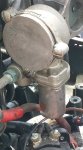
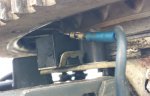
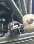
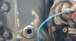
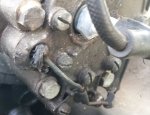
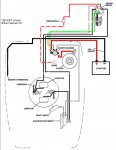
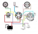
I am comparing the wiring from my 1965(?) 28 HP Johnson to this 1969 40 HP johnson and the wiring is different and I know I can do some damage if I wire it up incorrectly. My '65 had the solenoid external to the engine, installed near transom of boat with 5 wires going to engine, two battery leads, choke, two for upper and lower coils and the safety switch, (If I recall correctly)... This Motor has a solenoid internal to the engine and the wiring harness connection, however I do not have the other part of the wiring harness that connects to the ignition key set dashboard switches etc. I'm thinking that if I cannot source out the ignition wires set that plugs into my harnness, the easiest way would be to hook up my external solenoid and disconnect the internal solenoid, correct?.. However there are more leads in this engine than the '65. There is no choke however there is something connected to the carb that has a wire connected to the base (see pic madtom pic 1) and there are 3 wires connected to the center post of the vacuum cut-out switch, where I'm used to seeing only two. Madtom Pic 3 shows the wires that come from my external solenoid and would anyone be able to advise me on where those 3 wires are to connect? one tab you can see the blue tape, the other has some red tape(difficult to see) and then there is the thin wire that doesn't have a round tab put more of a flat connector (the shorter wire) the other 3 are choke, and the two positive/nagative leads).. Thank you.
 

Attachments

  • photo249327.jpg
    photo249327.jpg
    77.6 KB · Views: 2
  • photo249328.jpg
    photo249328.jpg
    83.5 KB · Views: 2
  • photo249329.jpg
    photo249329.jpg
    205.4 KB · Views: 2

MadTom

Seaman
Joined
Aug 23, 2011
Messages
66
OK, so I've realized that pic 1 is for the electric choke, so now I'm left with the other 3 wires to connect.
 

F_R

Supreme Mariner
Joined
Jul 7, 2006
Messages
28,226
No Title

My guess is that somebody added that blue wire for a tachometer (They could have gotten the same thing from the key switch though). Ignore the electric shift and generator stuff from this diagram if you don't have them.

EDIT: If no generator & ammeter, connect red wire directly to key switch, and brown wire will not be used.
 

Attachments

  • photo234594.jpg
    photo234594.jpg
    231.1 KB · Views: 1
Last edited:

MadTom

Seaman
Joined
Aug 23, 2011
Messages
66
thank you F_R ... so can I simply disconnect everything that is connected to the existing wire harness?... also If you look in the pic under the blue cable you mention, there is a black cable that seems to goes nowhere and the end of this wire is frayed.
 

F_R

Supreme Mariner
Joined
Jul 7, 2006
Messages
28,226
I don't know what kind of life that motor has had or what somebody has done to it. Forget everything you know about it and wire it up according to the diagram.
 

MadTom

Seaman
Joined
Aug 23, 2011
Messages
66
and do you recommend to completely remove the harness and anything that is wired to it, to avoid any shorts etc.?.. thank you
 

F_R

Supreme Mariner
Joined
Jul 7, 2006
Messages
28,226
You have to be the judge of that. You are the guy there looking at it. What I am saying is make sure each component is connected the way it is supposed to be, according to the diagram.
 

MadTom

Seaman
Joined
Aug 23, 2011
Messages
66
Does iBoats.com sell an ignition switch I can use for this motor? - the one I have is Merc switch and the poles are labelled differently. If so, please direct me to the specific OMC ignition switch I would need. Thank you!
 

MadTom

Seaman
Joined
Aug 23, 2011
Messages
66
No Title

Thank you F_R... would you be able to confirm the following pics : Madtom2 is the safety switch?.. Madtom3 there is a secondary wire (not connected -has connector end) that follows the wire from the center pole of the vacuum cut-out switch it seems to connect to the lower coil. What is this? - Is this the connection to the emergency 'kill" switch which kills the engine? madtom4 is a threaded hole? what is this for and do I need something connected to it?...Madtom1... what is this wire for? and where should I connect it to?. Did not have this on my 65 motor. Thank you once again. have fun on the water this weekend.
 

Attachments

  • photo249818.jpg
    photo249818.jpg
    219.6 KB · Views: 2
  • photo249819.jpg
    photo249819.jpg
    187.4 KB · Views: 2
  • photo249820.jpg
    photo249820.jpg
    249.7 KB · Views: 2
  • photo249821.jpg
    photo249821.jpg
    279.6 KB · Views: 2

MadTom

Seaman
Joined
Aug 23, 2011
Messages
66
No Title

Please respond, please help!... how do I confirm which wires goes to the upper coil? I hope I can safely assume the wire which leads from my centre pole of vacuum switch is the lower coil, but then in the madtom 3 pic, the only other wire that leads into the coil area is the one shown with the connector (which in previous post I thought was provided to ground out the coil, but now I think that doesn't exist and that wire must be the upper coil.... Theses two wires are different gauges. This is the wiring flow chart I am following provided here on iBoats. The "M" on ignition switch besides the "A" pole goes to centre pole of vacuum switch (lower coil). The "B" goes to positive connection solenoid. The "A" goes to choke switch. The other "M" goes to wherever the upper coil wire is located, correct? also, attached is a wiring diagram for the kill switch ? Is this correct, required or does the ignition switch suffice? - I did read a previous post where it was said the two coils should never connect to each other but thats what this kill switch config does and I believe the function of the ignition switch is to cross the two coils when ignition is in the off position, correct?
 

Attachments

  • photo250098.jpg
    photo250098.jpg
    94.1 KB · Views: 1
  • photo250099.jpg
    photo250099.jpg
    48.3 KB · Views: 1
Last edited:

jimmbo

Supreme Mariner
Joined
May 24, 2004
Messages
13,670
Thank you F_R... would you be able to confirm the following pics : Madtom2 is the safety switch?.. Madtom3 there is a secondary wire (not connected -has connector end) that follows the wire from the center pole of the vacuum cut-out switch it seems to connect to the lower coil. What is this? - Is this the connection to the emergency 'kill" switch which kills the engine? madtom4 is a threaded hole? what is this for and do I need something connected to it?...Madtom1... what is this wire for? and where should I connect it to?. Did not have this on my 65 motor. Thank you once again. have fun on the water this weekend.


Madtom1 is the overheat sensor wire
Madtom2 is the starter interrupt switch
Madton4 the hole is the air inlet for the hot air auto choke. Been on 40hp starting in 1964, 1960 - 63 had a hot water choke. In 70 or 71, auto choke was replaced a thermal electric, or straight electric choke

Madtom3- has a wire cut. From you description, it comes from the cut out switch?

in Madtom2, it shows some wires with very poor insulation, and it is a lot like if you see one mouse in your house, you can bet there are a lot more.

In your 1st post, there is a picture of the wires lying on the boat. It looks like one has no connector? where does the other end of it trace to?

Also in the pic in your first post, the one showing the vacuum cutout, there appears to be a wire behind the blue wire. is it and where does it go?
 
Last edited:

MadTom

Seaman
Joined
Aug 23, 2011
Messages
66
Thank you Jimmbo... So the air inlet can/should be left as is, correct? No need to worry about overheat sensor wire, correct? I believe the connector (not really cut wire) in Madtom 3 is for the upper coil connection. It is taped along with the center pole wire from cut-off switch assume for lower coil(was already in place). What about the proper way to wire in the emerge kill switch?
 

jimmbo

Supreme Mariner
Joined
May 24, 2004
Messages
13,670
Thank you Jimmbo... So the air inlet can/should be left as is, correct? No need to worry about overheat sensor wire, correct? I believe the connector (not really cut wire) in Madtom 3 is for the upper coil connection. It is taped along with the center pole wire from cut-off switch assume for lower coil(was already in place). What about the proper way to wire in the emerge kill switch?

I edited my last post as you were posting

The 'connector' doesn't appear to be connected to anything, does it have two wires going in one end?
 

MadTom

Seaman
Joined
Aug 23, 2011
Messages
66
unclear on what "two wires going in one end", sorry... I'm assuming that connector was to connect to the ignition switch for the "upper coil", since it is taped along with the other wire that goes up into the magnetos from the center pole of cut-out switch, which would indicate the wire running into the lower coil. of course, LOL , just as I'm making some head way, I stupidly removed the pivot pin in error. realized what I did just as it came out.... can't get that back in now.... argh..
 
Top