1969 Selectric 40hp wiring help needed

eclipseturbors

Petty Officer 2nd Class
Joined
Apr 17, 2009
Messages
141
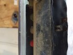
So I bought a Selectric model. It is clean, titled, and the right price. I'm accustomed to Mercs, but this motor fits the bill perfect for my 1958 Texas Maid. Except, the wiring in it was pretty well corroded through in alot of places. The PO cut some wires I'm guessing to remove some parts? I found a 1968 wiring diagram to work off of. I noticed I am missing a voltage regulator. I saw an old post that one for a Harley will work part # 381-309 but that post was for a different motor. Also, there is no fuse block or junction box. They threw in a starter solenoid in a box with the harness, cut off switch, and AMM meter (which is pretty cool). My questions...
Will the voltage regulator for a Harley work for my model and do I need that cut off switch? I do plan on retaining the dummy light. Do I mount the starter solenoid and voltage regulator under the hood?
This forum is the best around! Thanks in advance!
 

racerone

Supreme Mariner
Joined
Dec 28, 2013
Messages
38,415
I believe the 69 models had the voltage regulator and solenoid mounted on the lower cowling.-------And yes you need the cutout switch installed.
 

eclipseturbors

Petty Officer 2nd Class
Joined
Apr 17, 2009
Messages
141
Thanks. The posts on the cutout switch look a little rough and I'm sure a replacement won't be cheap. I'll clean it up and see what I get. Can you be almost positive that the solid state regulator will work? lol
 

F_R

Supreme Mariner
Joined
Jul 7, 2006
Messages
28,226
Depends on just what Harley regulator you are considering. You need the 10 AMP one for DC Generators. It was used on 1965-69 Harley Big Twin models and 1965-77 Sportster models.
 

eclipseturbors

Petty Officer 2nd Class
Joined
Apr 17, 2009
Messages
141
http://www.jpcycles.com/product/381-309

That is the one I'm considering. Also, I've ran into a new problem. There is a plug missing for the micro switches on the controls. I have the 2 wires for the shift solenoids, but not 100% on where they go on the bottom of the switch on the controls. The diagram has one wire from the ACC side of a start switch. I just don't want to confuse FWD and REV.
 

racerone

Supreme Mariner
Joined
Dec 28, 2013
Messages
38,415
12 volts is applied to green to get forward.-----12 volts is applied to blue to get reverse.
 

F_R

Supreme Mariner
Joined
Jul 7, 2006
Messages
28,226
As far as I know, that is the Harley regulator. But understand, I don't know a lot about Harleys.

You absolutely must have the correct switch for electric clutches. The look-alike switch for Hydro-Electric shift will cause catastrophic damage to the electric clutch lower unit. Don't assume, check it out with a multimeter.
 

eclipseturbors

Petty Officer 2nd Class
Joined
Apr 17, 2009
Messages
141
No Title

I did a terrible job of asking my question. I have these 3 spade connectors. One gets power from my ACC side of my ignition switch. Which one goes where?
 

Attachments

  • photo244462.JPG
    photo244462.JPG
    29.5 KB · Views: 0

F_R

Supreme Mariner
Joined
Jul 7, 2006
Messages
28,226
Sorry, too many years, too many tears to remember. But they were marked when they made it. markings may be gone. But you can figure it out with that multimeter I mentioned. Should show zero ohms between battery (ACC) and one of the remaining two when the forward button is pushed. That is the green wire. Should show zero ohms between ACC and remaining terminal when reverse button is pushed. That is the blue wire. There should be no continuity (high ohms or infinity) between any terminals when neutral button is pushed.
 

eclipseturbors

Petty Officer 2nd Class
Joined
Apr 17, 2009
Messages
141
So far, so good. Thanks for all the help! Turns out the switch was labeled on the bottom after a cleaned the dust off. I plan on ordering the Harley part number today for the voltage regulator. Does anyone know a good part # for a starter solenoid that will fit under the hood hopefully that I can pick up locally?
 
Top