1976 Evinrude 15655a 15hp no spark

Cdubb2010

Petty Officer 3rd Class
Joined
Apr 22, 2014
Messages
79
Alright, you folks here have helped me out many times before let's see if you can again.

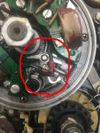
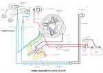
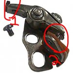
I picked this motor up in a horse trade deal last week. Guy I got it from moonlights as a marine mechanic and it was put on the back burner. He put one new coil pack on it, new fuel line and carb got rebuilt but it has no spark. He thought it was in the kill switch ( this one is mounted by the choke not on the tiller as some I've seen). We pressed in the kill switch and pulled it over and got no spark, so we pulled the switch and tested it with a multi meter and the switch is indeed bad. So I linked the three wires going to it together and I still have no spark. Is there a fault in how I tested the kill switch theory? So I moved on amd popped the flywheel off to look in there, nothing seemed out of the ordinary until we looked at the contact set (so the parts store has them listed as). They are supposed to be at .020 and one side is touching the other one is close to being right but is too far out. Would this cause no spark? I'm used to working on cars, this is forgin to me to a point. The attached photo shows the side that is touch on one side of the arm. Also if some one has a wiring diagram they can post that would be very helpful or even a link to a service manual.

Regards
 

Attachments

  • IMG_3549.JPG
    IMG_3549.JPG
    198.4 KB · Views: 2

F_R

Supreme Mariner
Joined
Jul 7, 2006
Messages
28,226
No Title

Your kill switch, as you describe it, doesn't sound right at all. In the first place, there should be two wires going to it, not three. And it should have spark with those two wires completely disconnected, not connected together as you attempted. Connecting them together via the pushed-in switch is what kills it.

On to the contact set (breaker points). You have the infamous Lo-Tension Magneto that has driven so many people crazy. The overwhelming majority of no-spark problems are caused by dirty or improperly adjusted points. And BOTH sets must be good in order to work. Yours appear to be dirty in the picture. As for touching, they should be touching until opened by the high spot on the cam. They should open .020" at their widest opening.
 

Attachments

  • photo280713.jpg
    photo280713.jpg
    218.9 KB · Views: 4

OptsyEagle

Lieutenant
Joined
Sep 13, 2006
Messages
1,359
There should be a mark on the points cam that says "set", I think. The points rub bar should be positioned on that mark and when it is the point gap should be set to 0.020". To clean the points, take a very fine points file and file the mating surfaces very lightly. Then blow with compressed air. Take a white business card dipped in lacquer thinner and pull it though the points and again blow with compressed air. Now don't touch them again.

I suspect your kill switch was fine. Not sure what the 3rd wire was but as FR said, if you push in that button on the front you will ensure that the motor gets no spark. That is why they call it a kill switch. As you noticed, no spark kills it quite well.

Use NGK B6HS spark plugs if you can. That motor tends to want to foul the recommended champions quite quickly. Especially if you want to use the motor for slow trolling. That model prefers to be run full out.
 

Cdubb2010

Petty Officer 3rd Class
Joined
Apr 22, 2014
Messages
79
Thanks for the replies and diagram!

First off it seems one of the contact sets are touching no matter what setting it's on. The other side does move at least, also it was in the set position when this photo was taken. The kill switch's third wire is just a tail that runs into the battery cables, I realize it serves no purpose with out having a battery hooked up but since the three were always together I rigged them up anyways. Which I guess was the wrong thing to do, the circuit being completed is what kills it not being open if I'm understanding correctly now?

So when setting these you measure the cam side "business end" of them only or does the other side on the contact set need to be at .020 as well? Also looking at them it looks like I have to unscrew the coil pack to get to what I think is the adjuster screw. Is this correct?
 
Last edited:

Cdubb2010

Petty Officer 3rd Class
Joined
Apr 22, 2014
Messages
79
The kill switch looks like one of the lanyard type ones you'd see on a snowmobile or jet ski. If I can do away with it I'd like to. I don't feel it's necessary on a sailboat (Bristol 24) down in a outboard well.
 
Last edited:

F_R

Supreme Mariner
Joined
Jul 7, 2006
Messages
28,226
Closed kill circuit kills it, open circuit runs it. Neither wire should be connected to the battery cables, per diagram.
 

Cdubb2010

Petty Officer 3rd Class
Joined
Apr 22, 2014
Messages
79
Actually, that is one of the alternator coils in the picture. A small corner of the ignition charge coil is showing on the opposite side.

Is said "oozing" normal? Looks like wax to me
 

OptsyEagle

Lieutenant
Joined
Sep 13, 2006
Messages
1,359
Yes. When you push the kill button a metal piece touches the two wires and completes the circuit...and grounds out the spark.

Not sure what you mean by business end or contact end. To adjust the points, move the rub bar of the points to the set position. Loosen the slotted screw that you see between the red shrink wraps in the photo you posted in your first post. Then with another slotted screwdriver insert it in that groove that appears to be at around 5 o'clock on your amature plate and you should be able to push the point gap open. It is the gap between the metal contacts that you are trying to set. When you have it where you want it, just tighten up the slotted screw that you previously loosened. Err on the side of larger gap since the gaps tend to decrease with use as the rub bar erodes. I aim for 0.020" to 0.021" gap. This is done for both points. I will now usually move the throttle to some other level (mid range is good) and verify that the point gap didn't change. This tells me my timing advance is being maintained well. Now, whenever you measure or reset a gap, always remember to clean the points with lacquer thinner since most feeler gauges are absolutely filthy as are most fingers when working on these things.

If you want you can check for spark without torqueing down the flywheel. Just put the flywheel back on and tighten up the center nut fairly snug. You can then pull on the starter rope and verify that you are getting a good spark (should be able to jump a 3/8" gap). Just make sure that the motor NEVER starts up until you have the flywheel torqued down to the correct specified level.

Your driver coils looks a little different from mine but if you have the flywheel off, set and clean the points and see if you are getting spark. If you are then I am going to say that oozing is normal and if you don't get good spark we can have a discussion about it. You really don't want to have to replace that driver coil. They don't give them away but they rarely fail so I bet you will see a bright blue spark when you set and clean up those points.

On my 1976, 15Hp motor. If I leave it without use for more then 3 years, I will almost certainly have to clean my points. That is why I try to get it in the water at least once per summer. That being said, it doesn't hurt to reset the point gaps every 3 or 4 seasons of use, since those gaps tend to decrease with use. It is a slow problem and one you hardly notice until you reset them again. That motor, if properly tuned will pin you to your seat when you open up that throttle, if the motor is properly trimmed on most 14 foot aluminum boats.
 
Last edited:

OptsyEagle

Lieutenant
Joined
Sep 13, 2006
Messages
1,359
One last thing I would do if I were you is to verify that the carburetor is properly synchronized with the motors timing advance to ensure the spark timing is perfect over all RPM ranges of the motor.. The reason this is best done now is if you need to adjust it, having the flywheel off makes it a lot easier. When you turn the throttle you will observe that the throttle cam under the flywheel starts to turn and pushes on the roller on your carburetor. If you look closely you will see an arrow indented on the throttle cam. That arrow should be right in the middle of the carb's roller JUST when it touches the throttle cam. If it is, then the motor is good to go. If it is not, there are two 5/16" hex screws on the starboard side of that throttle cam, that when loosened, allows you to position the throttle cam properly for this purpose. If the flywheel is on the motor you will find that you would need a very thin wrench to loosen and tighten those hex nuts. That is why I am suggesting you check this now.
 

Cdubb2010

Petty Officer 3rd Class
Joined
Apr 22, 2014
Messages
79
1 is the business end 2 is the contact end. I have no idea the Christian names for any of this, so my apologies for being vague. Does 1 or 2 need to be at .020? Number 2 is what's bottomed out on one side and the other it's not making contact at all, greater than .015 which was the only feeler gauge we had on hand. It's worth noting the one side's #2 is bottomed out in all throttle postions.
 

Attachments

  • IMG_3552.JPG
    IMG_3552.JPG
    99.3 KB · Views: 1

racerone

Supreme Mariner
Joined
Dec 28, 2013
Messages
38,461
# 2 needs to be at 0.020" and at the right time.-----Research using a meter and timing marks to set the points for best results.
 

OptsyEagle

Lieutenant
Joined
Sep 13, 2006
Messages
1,359
OK. Put the #1 (rub bar) to the set position on the cam and ensure #2 (contacts) is at a 0.020" gap. Do this for both point sets. Make sure the surfaces of #2 are filed very lightly and cleaned impeccably well and you should be good to go.
 

Cdubb2010

Petty Officer 3rd Class
Joined
Apr 22, 2014
Messages
79
Thank you everyone, I think I have the info I need now. Will update, hopefully this does the trick.
 

Cdubb2010

Petty Officer 3rd Class
Joined
Apr 22, 2014
Messages
79
Alrighty,

So points are cleaned and set (also got that little cam timed in with the carb roller) and we still have no spark. Soooo what now?

It's worth noting we tried it with the kill switch wires together and apart with no change.
 
Last edited:

oldboat1

Fleet Admiral
Joined
Apr 3, 2002
Messages
9,612
small margin on that one for setting points -- comfortable with what you have based on the SB crosbyman posted? How about the ignition coil and the mag plate grounds?

Think that would be a single magnet system, but make sure the magnet is good. Additionally, the air gap between the rotating magnet and the stator and driver coils has to be correct. That's usually a matter of making sure the laminations are dead on flush at the mounting posts. Make sure the wires are tucked in so they don't contact the flywheel, and the wiring leading out to the ignition coils is not pinched (no abrasion).

Test for spark with an adjustable open air tester -- think you should see spark at 3/8 to 5/16". The spring connectors inside the boots need to have a solid contact with the wire core, and your tester needs a solid ground. If you crank it in low light, can check for leaks in the wires or coil casings.

Make sure the starter and battery are strong, and the engine is cranking fast. (I usually do compression testing at this point as well, and make a note of the readings.)
 

racerone

Supreme Mariner
Joined
Dec 28, 2013
Messages
38,461
I think there are 2 sets of magnets on those.-----Maybe the driver coil is no good, test it or have ot tested at a shop.
 
Top