Re: 1989 85HP Force - None of my gauges works
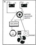
The alternator on your engine does not have energised fields. Rather, it has permanent magnets in the flywheel rim and a stator. The Perco isolator is a general battery isolator switch and has a circuit to protect the diodes in an automotive type alternator. No wires from your alternator need to be attached to the small field terminals. Simply connect the large battery wires to the appropriate power terminals on the Perco switch.
Even though your alternator does not have diodes and energised fields, it is possible to damage a stator by not having a load on it while running, so do not leave the isolator in a position where the battery is disconnected from the alternator while running. It will not, however, hurt the stator to switch from one battery to the second while running as long as the change-over is done quickly. It is better though, to switch with the engine not running if possible.
The tachometer circuit signal is the purple wire. It is one of the AC terminals on the rectifier. You will also need to run a ground and a power wire to the other two terminals on the tach. Power can be attached to the "I" or "A" terminal on the ignition switch. The alternator on your engine is a 20 pole one and there is a special tach for Chrysler, Force and Mercs. If you have a standard 12 pole tach, it will not read correctly.
The orange wire is signal for heat. Unless your engine has a temperature sender, the gauge will not work. Usually the included sensor on the engine is a simple bimetal switch that closes when the engine overheats. SO: If you have a gauge and want to use it, you must buy a sending unit to screw into the top of the head where the stainless pipe plug is.
If you simply want to use the buzzer or an indicator light, run power from the "I" or "A" terminal on the ignition switch to one side of the indicator and attach the orange wire to the other side.
There is a wiring color chart attached to the exhaust cover of the engine. Be certain that the cable from the ignition switch is attached to the engine terminal by the starter with the wires in the correct order.
Also double check the installer's work: The ignition switch should be wired Blue to one "M" terminal, White to the other "M" terminal, Red to "B", Green to "C", and yellow to "S". No other engine wires are attached to the ignition switch. "I", or on some switches "A", is a terminal that only has 12 volts when the switch is on and is used to power "A"ccessories and gauges