1989 Merc V150 No Alarm Beep

Dale Lee

Cadet
Joined
Mar 8, 2020
Messages
12
When the key is turned on there is no beep to indicate the alarm module is working. I have tested the beeper horn and it does sound when powered and grounded. 12 volt power is getting to the purple wire on the alarm module. I have removed the oil cap with the ignition "on" and of course there is no beep, beep, beep. The Mercury Parts Catalog says that the alarm module for my motor serial # is a 41470a15 so I bought a used one online. When I pulled the original module I found it had 41470a14 stamped on it. The "15" replacement had a short purple wire with a plug on the end while mine had a long wire that connects to the terminal block. The "15" replacement also had a solid tan wire while my the original had a tan/blue wire. I made a temporary extension for the purple wire and hooked up the replacement module with the same results, no beep. I am struggling, is the replacement module bad too or is the 41470a15 not compatible or do I have another problem? Fortunately, I can return the used replacement module.

When I do a search on the original 41470a14 part I only get links to used parts on ebay. I get part not found on all of the major boat part sites. I can find new and used 41470a15 parts on many sites and Mercury states that the "15" has been superseded by 41470a26 but are these truly compatible replacements?

New parts are $350+ so I want to make sure I am solving the right problem or worse yet not blowing the new module when I hook it up.

Are there other causes for the alarm not beeping? Are there other tests I can run to confirm or rule out the alarm module?

Anyone have any input on the compatibility of the 41470a14 vs "15" and "26" part numbers?

Thanks very much for any input or suggestions.
 

sam am I

Commander
Joined
Jun 26, 2013
Messages
2,169
Trace the tan/blu wire coming from the alarm module, it runs all the way from the module to the beeper (under the dash?) and is the negative side of the beeper's power, perhaps the wire is broken somewheres along its path to the dash?
 

Dale Lee

Cadet
Joined
Mar 8, 2020
Messages
12
The beeper does beep at the throttle control when I manually ground the tan/blue wire so that seems to indicate the wiring is good, right?
 

sam am I

Commander
Joined
Jun 26, 2013
Messages
2,169
Yes if you're grounding the tan/blue wire back at the alarm module, you're in fact testing the entire path......... Not sure if the module goes silent if one of its particular inputs goes missing, i better do some digging
 
Last edited:

sam am I

Commander
Joined
Jun 26, 2013
Messages
2,169
You never said......The motor starts and runs ok?

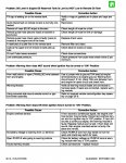
Click image for larger version  Name:	135-150-175-200-225 hp.jpg Views:	1 Size:	457.2 KB ID:	10838024

As I recall from a few years back bench testing mine, there were/is certain initial powering up states/parameters that the sensor/s must meet and be in in order for the alarm module to give its tell-tale power up beeping sequence .......see above attachments.
 

Attachments

  • 135-150-175-200-225 hp.jpg
    135-150-175-200-225 hp.jpg
    457.2 KB · Views: 2
Last edited:

Dale Lee

Cadet
Joined
Mar 8, 2020
Messages
12
I noticed it did not beep last fall when I started it to finish winterization. The engine ran fine with plenty of blue smoke in the driveway so i wasn't too worried. I ran it long enough for the engine to come up to temperature to make sure the thermostat was functioning. I didn't notice any other problems.

The information you provided still points to a warning module failure but it would be nice to know for sure, if that is possible. Thanks for your suggestions and sending the attachments. If you think of anything else, please let me know.
 

sam am I

Commander
Joined
Jun 26, 2013
Messages
2,169
You're sure the oil injection pump's rotational sensor isn't bad or disconnected? Seems a bit off that two (the original and the replacement) module are both bad and have failed in the same way (no initial power-on beeps)...........If it is for sure connected properly (no corroded bullet connectors and the like)wondering if perhaps we can figure a way to emulate the sensor? You know, trick the alarm module with a dummy connection........Hmm

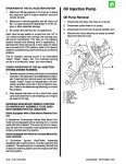
More info FWIW below

http://continuouswave.com/whaler/ref...Injection.html
 
Last edited:

Dale Lee

Cadet
Joined
Mar 8, 2020
Messages
12
I agree, it is a big concern that replacement alarm module also fails. However, it is a used part so it may have come from a failed engine???? The reason I ordered it was that it had a one year warranty as the seller stated that there was no way to bench test the part. The rotational sensor is connected and all of the bullet connectors look good. I would love to test the sensor but I guess a simple continuity test will not do the trick. I would hope a failed sensor would default to a "beep" vs. "no beep" situation but I'm sure anything can happen. I posted here because there is a lot of information on constant beeping issues but almost nothing the no-beep problem I have.

Thanks again for sending the oil injection information. I found that from one of your posts from several years back. I am keeping copies of all of this stuff for future reference. If you think of anything else let me know.
 

sam am I

Commander
Joined
Jun 26, 2013
Messages
2,169
The rotational sensor is connected and all of the bullet connectors look good.

Good.....

I would love to test the sensor but I guess a simple continuity test will not do the trick.

1) Not really no, got a volt meter? With Ig. "on", check the sensors white wire to ground, it should be around 12V.

2) Next, check the blue-white wire to ground, should around 4'ish to 5'ish V

3) Next, take plugs out (recommended) and still with ig "on", slowly rotate the crank shaft, at some point through 2 rev's of the cranking, the blue-white voltage should drop down to around 1V momentarily as you continue to crank.

I would hope a failed sensor would default to a "beep" vs. "no beep" situation but I'm sure anything can happen.

On power up, I think the alarm module looks/checks for that 5'ish V level on its blue-white wire, if it's not present, the module stays silent as a diagnostic, thus indicating a sensor issue. See #2 above..

So on the flip side.......

My thought here is if this is truly the case on how they "go/no go" their alarm module/s, we should be able to bench test the module w/o a sensor by simply putting 5V on the blue-white wire during power up and the alarm should sound.
 
Last edited:

Dale Lee

Cadet
Joined
Mar 8, 2020
Messages
12
I tested 12 volts on the white wire coming out of the alarm module with the key on but only 1 volt on the blue/white wire coming out of the alarm module. There is no voltage on the white wire (sensor side) with the blue/white wire plugged into the module and no voltage on the blue/white wire (sensor side) with the white wire plugged into the module. Should I expect to see 4-5 volts coming out of the blue/white sensor wire with the white wire plugged in? If that is the case why would I see 1 volt coming out of the blue/white wire on the alarm module which would be fed into the sensor? Something is not making sense to me or maybe I am interpreting your instructions incorrectly.

I have not pulled the plugs and run the rotation test. It will take me some time to rig up some jumper wires for that test. Can I rotate the prop for this test or should I use the starter motor. I could use your interpretation on the my results above before doing the rotation test.

Thanks for your detailed instructions!

Thanks again, this may be a strong
 

sam am I

Commander
Joined
Jun 26, 2013
Messages
2,169
Sry, I wasn't explicit........leave everything hooked up normal.

The white wire path is the 12V feed into the sensor, the blue/white wire path is sensor's output sig feeding into the module. With everything hooked up, you should see around 5V on the blue/white wire path with a 1V pulse somewhere's during the rotation.


Think perhaps the module has a internal pull up resistor where when the magnet on the bushing passes by the hall effect pickup, it pulses low (the signal is a "active low")

Can't really use the prop and the stater may spin it too fast to catch.....Can you put a socket on the flywheel nut and ratchet it slowly?
 

sam am I

Commander
Joined
Jun 26, 2013
Messages
2,169
stater may spin it too fast to catch....

STARTER may spin too fast to catch THE PULSE.....Sry was multi tasking, Tax season ya know

Also, when I say "with a 1V pulse", I mean the 5V should momentarily and suddenly drop down to around 1V then pop back up to 5V.....

Again sry, I think do this too much and forget to be clearer.
 

sam am I

Commander
Joined
Jun 26, 2013
Messages
2,169
oil inject.jpg
This should help......I perhaps have the logic backwards, it may stay 1V and be a 5V pulse every 2 rev's, and it's active high.

I've found conflicting reports and Merc's trouble shooting guide isn't clear (to me anyway), my boat of covered for winter else i'd put a meter on it. I keep looking around to be sure
 

Dale Lee

Cadet
Joined
Mar 8, 2020
Messages
12
No worries, the devil is in the details. I really appreciate all of your help. In order to run the test I need to check for 5v and intermittent 1v pulses on the blue/white wire.while connected to the module. My read is that your interpretation seems correct. Since I cant\'t stick a probe in the bullet connectors while they are connected, I will need to make a spliced jumper wire. One end will connect to the blue/white wire on the sensor the other will connect to the blue/white wire on the module. I will have a an un-insulated splice in the middle where I can connect the red voltmeter probe. The black probe will be grounded. Does this test procedure sound correct? Cranking with a wrench sounds better than the pull cord.
 

sam am I

Commander
Joined
Jun 26, 2013
Messages
2,169
Yes, sounds right AND, just to re-iterate, we're not testing per-se to see if we get the actual pulses (we certainly can check for them at same time though) BUT, we're mainly for now, looking and are particularly interested in the initial power-up voltage level that the sensor sets and must be present and proper for the module to read.

Again, this level is dictated by the sensor and MUST be within certain limits (we think 5'ish volts) and be present upon powering up (Ig switched to "on") for this is what the module is expecting to read and then will in turn sound the power up sequence of beeps.
 

Dale Lee

Cadet
Joined
Mar 8, 2020
Messages
12
Got it. May get to it tomorrow since it is a good rainy day garage project and I am anxious to get this problem figured out! Thanks again for your research and help.
 

Dale Lee

Cadet
Joined
Mar 8, 2020
Messages
12
I rigged up my spliced jumper wire with some same sized bullet connectors so I would have solid connections. Here are my test results. 0 voltage reading on blue/white wire when the key is turned to ON. The crank test results in a periodic less than 1v. reading which lasts for about 11/4 revolutions then it goes back to 0v. After another 3/4 revolution the <1v reading reappears and lasts for another 11/4 revolutions. This cycle seems to repeat. Seems as though I may have a faulty oil motion sensor, as you surmised. Merc troubleshooting also lists "Drive system defective" as a possibility. Does this refer to the oil pump drive system? I think it is working but it is it worth testing as well? I don't have those procedures. Thanks for the detailed instructions!
 

sam am I

Commander
Joined
Jun 26, 2013
Messages
2,169
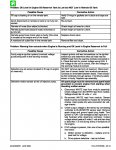
So if the 12V was present on the connected white wire (assume it was), then I'd be leaning towards bad sensor.....BUT! Why is it bad?


Weird readings too!......The levels are whacked obviously and It's almost as if the magnet that is on the bushing isn't rotating by the sensor probe properly......Hmmmm (insert nervous music BUT, you have blue smoke and runs okay)

Firstly though.......Double check ourselves on those logic levels if we can.

Unscrew the sensor's mounting screw and pop it out.......easy peesy.

Leave sensor still electrical connected properly, turn ig. to "on", re-test checking those levels again!! Ensure 12V still present on white wire and now blu/wht wire, same?

If so........Got a magnet? Pass it by the sensor's probe end(the tip)..........Any change on blu/wht wire?

If not, swap alarm modules.....

Re-test with ig. "on", ensure 12V still present on white wire and now blu/wht wire, same?

Repeat passing magnet by the sensor's probe end..........Any change on blu/wht wire?

If you can't get the blu/wht wire's voltage to *wiggle accordingly with either alarm module properly connected by passing a magnet by the sensor's head, i'd say....Bad sensor! Or two bad alarm modules?

Does the probe tip end of the sensor look normal machined? (more nervous music)


Else...........

Click image for larger version  Name:	Merc.jpg Views:	1 Size:	119.6 KB ID:	10839214
*Wiggle (technical eng. term) = jump up or down in voltage/logic levels like from 5V to 0V and such ;)
 
Last edited:

Faztbullet

Supreme Mariner
Joined
Mar 2, 2008
Messages
15,933
Ya gotta have 12V on purple when key is on for module to operate....If it don't self test the module is bad and this is a very common problem. If you just turn key on, crank it a few revolutions (don't want it to start so no primer) and leave key in the on position the alarm should sound in a few minutes as the module will "think" motor is running and not seeing the N/S change from the rotational magnet and sensor.
 
Top