I am helping my Nephew with is 1990 Sunbird Corsica, 2.3L Ford Cobra engine. He prepped it for first use. Put muffs on, started it, ran it for about 5 minutes. Took it to the launch, got it in the water and it wouldn't start. (classic, right?)
He brought it to my house, we put muffs on, it cranks fine, fires, dies as soon as the key is released from crank position.
I ran a jumper from B+ to the + terminal of the coil, he cranked it, it started and ran until I removed the wire.
I found a manual online, read as much as I could about the circuits, and troubleshooting, but the manual leaves a bit to the (at least my) imagination. If I am reading everything correctly, it seems that:
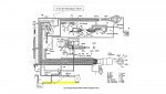
- With Ignition Switch in Crank, B+ to the coil comes from the Starter Solenoid direct to the Coil +
- With Ignition Switch in Run, B+ to the coil is from the Alternator, (Purple) into a splice, through a resistance wire (Red/Purple) to the Coil +
- From the same splice, a Purple wire runs to the ESA Module, and a Grey wire runs from the ESA to the Coil (-)
- I am guessing the ESA Module grounds the power to the coil briefly during a forward reverse shift.
I've attached the circuit diagram I am using.
What I am uncertain about is:
Is the Red/Purple wire actually a Resistance wire?
If the ESA Module is bad, or the micro switches are mis-positioned, and I disconnect the (Purple & Grey) wires going INTO the ESA Module and it runs, that should isolate the problem to the module or switches. Yes?
If above does not work, then is the issue likely the Red/Purple Resistance wire?
Any suggestions or guidance would be greatly appreciated.
TYVM,
John
He brought it to my house, we put muffs on, it cranks fine, fires, dies as soon as the key is released from crank position.
I ran a jumper from B+ to the + terminal of the coil, he cranked it, it started and ran until I removed the wire.
I found a manual online, read as much as I could about the circuits, and troubleshooting, but the manual leaves a bit to the (at least my) imagination. If I am reading everything correctly, it seems that:
- With Ignition Switch in Crank, B+ to the coil comes from the Starter Solenoid direct to the Coil +
- With Ignition Switch in Run, B+ to the coil is from the Alternator, (Purple) into a splice, through a resistance wire (Red/Purple) to the Coil +
- From the same splice, a Purple wire runs to the ESA Module, and a Grey wire runs from the ESA to the Coil (-)
- I am guessing the ESA Module grounds the power to the coil briefly during a forward reverse shift.
I've attached the circuit diagram I am using.
What I am uncertain about is:
Is the Red/Purple wire actually a Resistance wire?
If the ESA Module is bad, or the micro switches are mis-positioned, and I disconnect the (Purple & Grey) wires going INTO the ESA Module and it runs, that should isolate the problem to the module or switches. Yes?
If above does not work, then is the issue likely the Red/Purple Resistance wire?
Any suggestions or guidance would be greatly appreciated.
TYVM,
John