1991 90 hp Force ( Engine code 906x91c )

Dlubke

Cadet
Joined
Apr 8, 2019
Messages
12
1991 90 hp Force ( Engine code 906x91c )

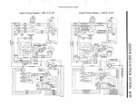
Does anyone have a wiring diagram of the trigger wires to the modules ? Bought a boat and all the trigger wires were pulled off. I was able to get spark on all 3 cylinders but I am unsure if the timing is in correct order from the trigger. Engine does not want to start. Was able to get engine running in a configuration but only 2 cylinders fired. When I wire it back so all cylinders spark it wont run. The trigger has 6 wires, 2 green, 2 orange, red , white/green. Could the orange and green wires backwards change firing order ? Thanks in advance.
 

jerryjerry05

Supreme Mariner
Joined
May 7, 2008
Messages
18,074
The wires are supposed to be a pair for each cyl.
The wire pairs should have continuity to each other.
If the trigger wires have continuity with more that one wire the triggers bad.

Unfortunately the color codes on the triggers has changed from year to year and model to model.
I've never seen a diagram that shows the actual color breakdown.


The only thing I have with reference to the color code:

Green/Orange
Red/White,Green
Orange/Green

I have a wiring diagram but can't copy/scan or load to this site.
If you want it?? Send me an email through a PM
 

Dlubke

Cadet
Joined
Apr 8, 2019
Messages
12
Yeah I will need a diagram because I don't know what set of wire pairs go for what corresponding cylinder as the wires have no labels. With the orange and green's it could be cylinder 1 or 2 … but I have no idea what pair should go to fire what coil and in what order.
 

legalfee

Petty Officer 1st Class
Joined
May 10, 2018
Messages
394
[No message]
 

Attachments

  • photo293561.jpg
    photo293561.jpg
    109.9 KB · Views: 5

Dlubke

Cadet
Joined
Apr 8, 2019
Messages
12
Thanks legalfee but that diagram only has 4 wires comming from trigger asembly not 6 also the color dont match up with mine.
 

Nordin

Commander
Joined
Jun 12, 2010
Messages
2,589
Dlubke that diagram from legalfee is for the Thunderbolt ignition system.
I assume your engine has the Prestolite typ.

As the PM at this forum do not work I can not send you the diagram.

I will try to explain any way.

#1 cyl
White/brown/yellow
White/brown/orange

#2 cyl.
White/brown/green
White/brown/red

#3cyl.
White/black/yellow
White/black/orange

Connection to terminal strip

White/brown/yellow to white/yellow #1 CDI box.
White/brown/orange to white/orange #1 CDI box

White/brown/green to white/green #1 CDI box
White/brown/red to white/red #1 CDI box

White/black/yellow to white/yellow #2 CDI box
White/black/orange to white/orange #2 CDI box.

Hope you understand, not so easy to explain.
 

Nordin

Commander
Joined
Jun 12, 2010
Messages
2,589
Well I checked one of my other sources.

#1 cyl
Orange
Green

#2 cyl
White/green
Red

#3 cyl
Orange
Green

#1 and #3 can be mixed up but then you can change them.
You can measure with a VOM which one of the orange and green that associated to each other.
The resistance between orange and green should read 48-52 Ohm.
 

jerryjerry05

Supreme Mariner
Joined
May 7, 2008
Messages
18,074
Each pair of wires should have continuity.
Continuity with other wires? Bad trigger.

You have to figure out the pairs??
Then try hooking up the 3 sets of wires and see if it runs??
9 different combinations to try :)

If the tags are off the pairs? then there's no way to ID which part of the trigger they go to :(
 

legalfee

Petty Officer 1st Class
Joined
May 10, 2018
Messages
394
Force with Prestolite
 

Attachments

  • photo307841.jpg
    photo307841.jpg
    145.4 KB · Views: 7

The Force power

Commander
Joined
Feb 3, 2019
Messages
2,350
I put a picture of prestolite trigger wiring with tags in my Idea book (it was the only way to upload)
maybe it is of any help
 

legalfee

Petty Officer 1st Class
Joined
May 10, 2018
Messages
394
Dlubke that diagram from legalfee is for the Thunderbolt ignition system.
I assume your engine has the Prestolite typ.

As the PM at this forum do not work I can not send you the diagram.

I will try to explain any way.

#1 cyl
White/brown/yellow
White/brown/orange

#2 cyl.
White/brown/green
White/brown/red

#3cyl.
White/black/yellow
White/black/orange

Connection to terminal strip

White/brown/yellow to white/yellow #1 CDI box.
White/brown/orange to white/orange #1 CDI box

White/brown/green to white/green #1 CDI box
White/brown/red to white/red #1 CDI box

White/black/yellow to white/yellow #2 CDI box
White/black/orange to white/orange #2 CDI box.

Hope you understand, not so easy to explain.

It sounds like he's got the trigger for the 85hp (see diagram I posted) It should work. I wonder how his modules are color coded. He could match them up using the 90hp diagram if the modules are color coded as such.
 

Dlubke

Cadet
Joined
Apr 8, 2019
Messages
12
well thanks everyone for the help, I have it figured out going to order a new CDI module. When testing the CDI module it was internally short causing only one coil to be fired at a given time. If #1 and #2 plugged in it would only fire #1, when #2 and #3 plugged in it would fire #2 and #3. When #1 and #3 plugged in it would fire #1 and #3. So after messing around I realised the only time #2 would fire is with #1 unplugged. So I then I went onto testing each trigger wire to #3 cylinder making sure I was not having any issues with my triggers.
 

jerryjerry05

Supreme Mariner
Joined
May 7, 2008
Messages
18,074
Change packs around if the #2 on pack #1 isn't firing.
3cyl. uses only 3 of 4.
If it was #1 then you'd need a new pack.
 

Dlubke

Cadet
Joined
Apr 8, 2019
Messages
12
Both packs are dead on #2 unfortunately i'm thinking someone tried this once already ran it for years then it died again so then they started farting around with wiring and got it all messed up.
 

The Force power

Commander
Joined
Feb 3, 2019
Messages
2,350
Before you replace a suspected "bad Pack" check the wiring

I found with my motor; that the wire terminals are not connected to the wires (under the shrink-tube)
You can verify this by pulling & wiggling the wires and wire(s) will just let go of the terminal
 

legalfee

Petty Officer 1st Class
Joined
May 10, 2018
Messages
394
On my 1995 90hp I replaced everything from the ignition switch to the spark plugs. I figured on a 24 year old motor why not. Only the stator was bad and I had a flaky coil.
 

jerryjerry05

Supreme Mariner
Joined
May 7, 2008
Messages
18,074
Unfortunately there isn't a direct test for the pack:(
It's a process of elimination, check everything else and if they all test OK???
Then the last thing is to change the pack.

NO FIRE OR INTERMITTENT ON ONE CYLINDER: 1. Check stator and trigger resistance, trigger wire sets read approximately 50 ohms between the wire sets (DVA .5V or more), OEM stator will read 680-800 ohms (DVA 180V or more) from blue to yellow. (CDI Stators will read 400-500 ohms). 2. Disconnect kill wire from one pack. If the dead cylinder starts firing, the problem is likely the blocking diode in the other pack.
 

Dlubke

Cadet
Joined
Apr 8, 2019
Messages
12
When performing resistance testing a bad connector would show up in your testing with either a OL or even with a bad connection way out of the normal resistances. Even with the said the only correct way to diagnose wiring issues is load testing the circuit. Monitoring voltage on a circuit is by far the best way. Iv seen a 0.5 ohm reading and wires but yet cannot carry the voltage. You can indirectly test a module if you have a cylinder that has known good spark. First remove all trigger from all cylinders keeping pairs together. grab each set of pairs and wire them to known good cylinder if you get spark on all three pairs triggers are good,you then test each coil with known good module feed. After ruling out all coils with spark your now left with 3 good triggers and 3 good coils you then test each module circuit individually. In my case both #2's were faulty on each pack. having a internal short in one packing causing #1 and #2 to fire at the same time not being able to carry the load it would take path of least resistance only allowing one hole to fire at any given time on that pack. Having a wiring diagram makes the world of difference when decided what wires belong on what circuit, In my instance I had no wiring diagram to perform pinpoint testing in the correct manor. You can with specification charts figure out what wire does what job but takes hours. Better to just have the correct diagrams for the job.
 
Last edited:
Top