25XD ('84 or '85) has one working cylinder and one that gets no spark - no voltage is reaching the spark plug.
I believe I've ruled out the ignition coils and that they are both functional. That leaves the stator and trigger windings, and the 339-7452 A7 ignition module.
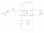
If someone has a schematic of what is inside the 339-7452 A7 ignition module, that would be mighty helpful in the troubleshooting process. Based on some rudimentary electrical measurements, I've attached a drawing of what I believe is in the module. Feel free to correct my sketch")
Looks like 1 stator winding is faulty. But there seems to be a diode connection between the inputs of the ignition module, so 1 good winding should charge both capacitors in the ignition module... is ignition module faulty as well?
-----------
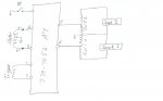
Here's what I know (referenced to attached drawings):
Spark 1 works. Spark 2 does not.
Winding Tests
1. Connect Coil 2 to E and Coil 1 to F. Spark 2 now works and Spark 1 does not.
Conclusion ? coils aren?t the problem.
2. Restore Coil 1 to E and Coil 2 to F.
3. Connect oscilloscope probe from A to ground. Meaures ~ 100V.
4. Connect oscilloscope probe from B to ground. No voltage.
Probable conclusion ? 1 faulty Stator winding
5. Connect oscilloscope probe to C. Measures ~ +4V pulse train, ~4ms wide, 66ms period.
6. Connect oscilloscope probe to D. Measures ~ -4V pulse train, ~4ms wide, 66ms period.
Probable conclusion ? Trigger winding ok.
7. Connect Stator A-1 to B and Stator B-1 to A. Spark 1 works. Spark 2 does not.
Probable conclusion ? depends on what is in ignition module.
Ignition Module Tests:
1. Connect ohm-meter Kill to A. Measures 0 ohms.
2. Connect ohm-meter Kill to B. Measures open. Put in Diode mode ? measures .526V.
Conclusion ? Diode b/t A & B
QUESTION ? given diode connection, could I live with only 1 working stator winding?
3. Connect oscilloscope to A. Close Switch1. Time constant => Ceff = 2 uF.
4. Connect oscilloscope to B. Close Switch1. Time constant => Ceff = 2 uF.
5. Short A to B. Close Switch1. Time constant => Ceff = 2 uF.
Conclusion ? At least 1 cap is good.
Question - What is expected capacitance? Is 1 of the caps defective?
-------
Have access to plenty of electrical equipment if there is some other test that needs to be run...
I believe I've ruled out the ignition coils and that they are both functional. That leaves the stator and trigger windings, and the 339-7452 A7 ignition module.
If someone has a schematic of what is inside the 339-7452 A7 ignition module, that would be mighty helpful in the troubleshooting process. Based on some rudimentary electrical measurements, I've attached a drawing of what I believe is in the module. Feel free to correct my sketch
Looks like 1 stator winding is faulty. But there seems to be a diode connection between the inputs of the ignition module, so 1 good winding should charge both capacitors in the ignition module... is ignition module faulty as well?
-----------
Here's what I know (referenced to attached drawings):
Spark 1 works. Spark 2 does not.
Winding Tests
1. Connect Coil 2 to E and Coil 1 to F. Spark 2 now works and Spark 1 does not.
Conclusion ? coils aren?t the problem.
2. Restore Coil 1 to E and Coil 2 to F.
3. Connect oscilloscope probe from A to ground. Meaures ~ 100V.
4. Connect oscilloscope probe from B to ground. No voltage.
Probable conclusion ? 1 faulty Stator winding
5. Connect oscilloscope probe to C. Measures ~ +4V pulse train, ~4ms wide, 66ms period.
6. Connect oscilloscope probe to D. Measures ~ -4V pulse train, ~4ms wide, 66ms period.
Probable conclusion ? Trigger winding ok.
7. Connect Stator A-1 to B and Stator B-1 to A. Spark 1 works. Spark 2 does not.
Probable conclusion ? depends on what is in ignition module.
Ignition Module Tests:
1. Connect ohm-meter Kill to A. Measures 0 ohms.
2. Connect ohm-meter Kill to B. Measures open. Put in Diode mode ? measures .526V.
Conclusion ? Diode b/t A & B
QUESTION ? given diode connection, could I live with only 1 working stator winding?
3. Connect oscilloscope to A. Close Switch1. Time constant => Ceff = 2 uF.
4. Connect oscilloscope to B. Close Switch1. Time constant => Ceff = 2 uF.
5. Short A to B. Close Switch1. Time constant => Ceff = 2 uF.
Conclusion ? At least 1 cap is good.
Question - What is expected capacitance? Is 1 of the caps defective?
-------
Have access to plenty of electrical equipment if there is some other test that needs to be run...