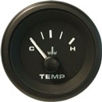
Re: ??????? adding a temp guage
O u t b o a r d e n g i n e t e m p e r a t u r e
m o n i t o r i n g
1. The temperature monitoring kit includes all parts to adapt to any of the situations above. Yamaha engines will
require an Adapter, P/N 61886P in addition to kit.
2. Because outboard engines use raw water for cooling and are mostly aluminum, they operate cooler than I/O
engines. Consult dealer as to the maximum operating temperature of your engine.
3. The sender in the kit has 1/8 - 27 NPT threads and has I.D. Code ?010? or ?060?* stamped on the hex.
4. Part number of the sender is 52320S010; the flat bracket is 54552; the ?Z? bracket IA55009.
5. Some engines include a threaded hole directly into a water line. The temperature sender can be threaded into
the hole, using no sealant on the threads. The threads create the electrical ground.
6. Some engines have a blind threaded hole for a temperature sender that does not enter the water jacket. After
applying thermal compound to the hole, (Sierra #18-9011 or equivalent) thread the sender in snugly, again using
no sealer.
7. Some Mercury engines have a blind hole flanked by two bolts. These are for securing the flat plate. First place
thermal compound in the hole (Sierra #18-9011 or equivalent) and drop the aluminum spacer in the hole.
Thread sender into bracket over hole until it hits spacer.
8. The Z bracket installation is used most often as it fits any engine. The Z bracket through hole is held by any one
of the engine?s cylinder head bolts. The sender is threaded into the bracket?s remaining hole down against the
cylinder head. Scrape the paint from the head under the sender to get good thermal transfer.
9. The kit is supplied with one sender. If a sender is desired on each cylinder bank on V type outboards, a double
pole ON-ON (Sierra #TG40180 or equivalent) switch must be used to switch sender input to the gauge.
The Gauge cannot accurately handle two senders at one time.
10. Testing the gauge for operation: Connect a hot wire to ?I? and ground wire to ?G?. Gauge should read below
the C. Next, short the ?S? terminal to ?G?. The pointer should go above the H. If the pointer sweeps this way,
the gauge is fine.
11. Testing the sender: At room temperature, with no wires on the sender, it should measure approx. 600-1000
ohms on test meter.
12. Replacement outboard sender IA96035 cannot be used with this gauge. The gauge will read very high. If the
sender is stamped ?010? or ?60? it will work correctly. If stamped ?230? it will not.
13. Every Teleflex Marine gauge can be identified by the part number printed on the side of the housing.
Please reference this part number when contacting technical service or replacing the original gauge.


Link to Teleflex gauges:
http://teleflexmarine.com/wp-content/uploads/2010/05/G13usa-premier_pro_black.pdf


