Adding ignition kill switch and lanyard 96 Johnson 88

Status
Not open for further replies.

73 Dolphin

Petty Officer 1st Class
Joined
Oct 8, 2008
Messages
306
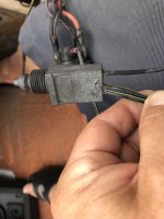
I was looking to add a kill switch next to my console mounted ignition.
It has 2 wires, They connect to the black/yellow and black. I do understand that by grounding the black/ yellow the engine stops.
But HOW do I connect the switch ?
Am I splicing the black yellow wire or just connecting the wire to the black/yellow
post? Am I cutting the black/yellow and bypassing part of the circuit?
I have seen the diagram showing the connections. I have seen posts.
I have seen videos but none of those actually has an image of how it is actually wired in real life.
I'm sorry if this sounds incredibly dense.
 

Chris1956

Supreme Mariner
Joined
Mar 25, 2004
Messages
28,087
My '98 Johnny came with a lanyard that fits the factory ign switch. The ign key can be used with or without the lanyard, as the lanyard, when pulled, turns the ign off.

Here is the OEM ign switch. If you have one, you can buy just the lanyard.


havoc_squad

Senior Chief Petty Officer
Joined
Mar 5, 2011
Messages
739
Yes, it would be easier if an 3 way six wire outboard ignition switch with overboard kill stop is used instead of a separate one.

If a seperate lanyard kill switch/stop is installed, all you are doing is wiring it in parallel to the wiring on the key switch so either the kill switch or the ignition switch can kill the ignition without being dependent on the other.

Always disconnect battery power before doing this because you can fry your outboard's ignition system if you accidentally send 12 volts to the black/yellow wire.

Black/Yellow stripe to Black/Yellow strip and Black ground to Black ground. Make 100% certain you verify the wiring is correct on your boat setup physically before doing that, otherwise you could fry your ignition system if there is color mismatching going on.

Doing a multimeter continuity test with the outboard harness adapter unplugged referencing the wiring diagram is a sure way to make sure it is right. You'll have to make some wire jumpers or buy one of those test lead kits.
 
Last edited:

Chris1956

Supreme Mariner
Joined
Mar 25, 2004
Messages
28,087
If you do need to add a separate ign kill switch, just splice it into the black and black/white wires. To kill the ign, they need to be connected together.

My OEM harness uses bullet connectors to connect to the ign switch. I would simply use some of those to make some "Y"s to splice in the killer switch.
 

73 Dolphin

Petty Officer 1st Class
Joined
Oct 8, 2008
Messages
306
Yes, it would be easier if an 3 way six wire outboard ignition switch with overboard kill stop is used instead of a separate one.

If a seperate lanyard kill switch/stop is installed, all you are doing is wiring it in parallel to the wiring on the key switch so either the kill switch or the ignition switch can kill the ignition without being dependent on the other.

Always disconnect battery power before doing this because you can fry your outboard's ignition system if you accidentally send 12 volts to the black/yellow wire.

Black/Yellow stripe to Black/Yellow strip and Black ground to Black ground. Make 100% certain you verify the wiring is correct on your boat setup physically before doing that, otherwise you could fry your ignition system if there is color mismatching going on.

Doing a multimeter continuity test with the outboard harness adapter unplugged referencing the wiring diagram is a sure way to make sure it is right. You'll have to make some wire jumpers or buy one of those test lead kits.
It has 2 wires. Black and white. Basically, then just connect
the white wire to the black/yellow terminal and the other to ground?
This way when I pull the lanyard the black/yellow is getting grounded and closing the circuit but when I insert the lanyard the circuit is re-energized?
 

73 Dolphin

Petty Officer 1st Class
Joined
Oct 8, 2008
Messages
306
It has 2 wires. Black and white. Basically, then just connect
the white wire to the black/yellow terminal and the other to ground?
This way when I pull the lanyard the black/yellow is getting grounded and closing the circuit but when I insert the lanyard the circuit is re-energized?
I should also add that it doesn't have the later ignition with the built-in kill switch. The boat is an 86.
 

racerone

Supreme Mariner
Joined
Dec 28, 2013
Messages
38,431
The spark stops when ignition is grounded out.----Circuit is OPEN for motor to run.-----Note---12 volts from the battery is NOT used to generate spark at the plugs.----That function is done by the spinning flywheel magneto.
 

havoc_squad

Senior Chief Petty Officer
Joined
Mar 5, 2011
Messages
739
It has 2 wires. Black and white. Basically, then just connect
the white wire to the black/yellow terminal and the other to ground?
This way when I pull the lanyard the black/yellow is getting grounded and closing the circuit but when I insert the lanyard the circuit is re-energized?

Do you understand the difference between parallel circuit and series circuit?

You must connect/wire the man overboard kill switch in parallel to the ignition switch for the black and yellow/black wires that both use. That way either the overboard kill switch or the ignition key has a path to send the yellow/black to ground to shut off the outboard ignition.

The colors on the man overboard kill switch wires don't matter. It is a normally open simple switch, one goes to each wire in parallel (one to black ground, one to yellow/black stripe)

If you connect them in series, you will have wired it wrong and you will have to both pull the man overboard kill switch and turn off the ignition key before the outboard will shut off. That is unsafe.

You really need to understand the basics of low voltage (12 volt/24 volt DC) electrical concepts to be working on outboard engine.

You seem to come the correct conclusion but I am concerned you do not know the why. That is what you really need to understand to do this correctly.

If you had concerns about wires mis-colored or incorrectly connected, that I could understand making this difficult to figure out. However, that is not the situation you are describing as the kill overboard switch is a simple switch.

Our answers won't help if people don't do some basic research ahead of time to understand as much as possible.

A helpful suggestion, draw the circuit out on a piece of paper. Then answer why it has to be that way and how the switches operate for allowing ignition and for killing ignition.
 
Last edited:

73 Dolphin

Petty Officer 1st Class
Joined
Oct 8, 2008
Messages
306
The switch has 2 wires. I was asking the easiest 2 points to connect in case someone had recently done this to their boat. ( pre 96 johnson ignition ) Thinking this might save me a little time and avoid unnecessary work in a tight space. Obviously you havent just installed said switch. You do not need to be so condescending. The diagrams from johnson showing kill switch wiring show exactly what I am saying.
What I was actually asking ( as if that matters ) is where is the best location for the wires.
 
Last edited:

Chris1956

Supreme Mariner
Joined
Mar 25, 2004
Messages
28,087
Is your current ign switch on the dashboard? If so, connect the kill switch to the black and black/yellow (or black/white) wires, on the ign switch. Find a place the the kill switch to be mounted, and you are done.

If you have a control with the ign switch mounted in it, it is the same connection, but you will need to fish the kill switch out of the control somehow.
 

73 Dolphin

Petty Officer 1st Class
Joined
Oct 8, 2008
Messages
306
Is your current ign switch on the dashboard? If so, connect the kill switch to the black and black/yellow (or black/white) wires, on the ign switch. Find a place the the kill switch to be mounted, and you are done.

If you have a control with the ign switch mounted in it, it is the same connection, but you will need to fish the kill switch out of the control somehow.
Thanks!!
 

Chris1956

Supreme Mariner
Joined
Mar 25, 2004
Messages
28,087
One more thing. Your OB needs the kill switch to connect the two wires, when the lanyard is pulled.

Some kill switches disconnect the wires when the lanyard is pulled, and some have both functions in one switch, and you get to choose which function you want to use.
 

Mangrucgc410

Cadet
Joined
Apr 11, 2022
Messages
6
I don’t want to start a new thread have similar situation Original kill switch has black, and 2 black yellow, 89 Johnson GT 200. Question is, do I take blk/ylw from engine to kill switch, and then other blk/ylw from kill switch to key switch. Can’t get the answer anywhere. Any help would be greatly appreciated,
thanks, Allen

Bottom 2 are both blk/ylw
 

Attachments

  • IMG_2884.jpeg
    IMG_2884.jpeg
    1.4 MB · Views: 8
Status
Not open for further replies.
Top