Amp draw 1990 Johnson tilt/trim unit

Mouse1

Cadet
Joined
Jul 13, 2016
Messages
26
Adapted a '90 Johnson tilt unit to a '72 Johnson 125HP. Have a Johnson relay box, need to know power draw to properly fuse the system.

Thanks.
 

Joe Reeves

Supreme Mariner
Joined
Feb 24, 2002
Messages
13,262
Depends on where you're taking the voltage from...... if from the ignition switch, it would already be fused via the 20 amp power fuse located a short distance in one of the small red wires connected to the starter solenoid. If taken directly off of the battery at some point, use a 20 ampere fuse.

No, I have no idea what amperage the PTT motor draws... BUT... if it blows that 20 amp fuse, you have a problem!
 

racerone

Supreme Mariner
Joined
Dec 28, 2013
Messages
38,504
Just curious----Any pictures of parts used and how they are installed ?
 

Fed

Commander
Joined
Apr 1, 2010
Messages
2,457
Only the control circuit is fused via the 20A fuse, the pump motor itself is not fused at all.
 

Joe Reeves

Supreme Mariner
Joined
Feb 24, 2002
Messages
13,262
Only the control circuit is fused via the 20A fuse, the pump motor itself is not fused at all.

Yeah, I was aware of that, but since this is a conversion, I figured from his explanation he would prefer the safety feature of fusing it.
 

jimmbo

Supreme Mariner
Joined
May 24, 2004
Messages
13,677
Adapted a '90 Johnson tilt unit to a '72 Johnson 125HP. Have a Johnson relay box, need to know power draw to properly fuse the system.

Thanks.

I too am curious as to how it was done. Any pictures?
 

Mouse1

Cadet
Joined
Jul 13, 2016
Messages
26
Thank you for the responses. Power will be from the battery via selector switch. Going to fuse that line, protect the whole system.
Pics to follow.
 

Fed

Commander
Joined
Apr 1, 2010
Messages
2,457
Fuse the T&T control circuit via the existing fuse and connect the T&T motor circuit to the battery positive side of the starter motor solenoid mouse.
Leave the 'whole outboard' connected directly to the battery just like Millions of other happy boat owners.
 

Mouse1

Cadet
Joined
Jul 13, 2016
Messages
26
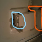
Sorry for the delay, holidays. Here are the pics of the mod. The motor is a '72 125HP the tilt unit from a '90 90HP.

Pic 1, the blue is the original mount. Orange is the lower trim mount point. Block between is 6061 aluminum, shaped and tapped.
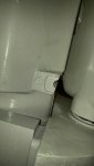
Pic 2, is where material was removed to clear steering section,
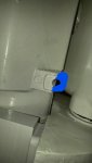
Pic 3, what was removed, was across the front of motor.
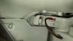
Pic 4, top holes were wider approx. 1/16th " for narrower top mounting holes on motor.
 

Attachments

  • photo284276.jpg
    photo284276.jpg
    369.6 KB · Views: 0
  • photo284277.jpg
    photo284277.jpg
    888.6 KB · Views: 0
  • photo284278.jpg
    photo284278.jpg
    857.5 KB · Views: 0
  • photo284279.jpg
    photo284279.jpg
    1,008.7 KB · Views: 0

Chris1956

Supreme Mariner
Joined
Mar 25, 2004
Messages
28,114
If you have an accurate ohmmeter, you can figure it out using Ohm's law. I = V/R, where I is current, V is voltage (12 VDC) and R is the resistance of the motor.

Let's say the resistance is 1 ohm. That means 12VDC / 1 ohm is the amperage or 12A. !/2 ohm resistance gives 24 Amps, 1/4 ohm gives. 48 Amps current.

You could also measure the gauge of the motor supply wires and look up the maximum amperage for that size.
 
Top