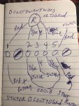
racerone, the numbers are for location , the results are like i wrote , the rectifier has no continuity to any wires on it nor to ground its completely open, the stator has continuity between the yellow and gray marked wire to the yellow /blue marked wire, i know its output is supposed to be around 4/5 amps so im going with a new rectifier on it, and im going to look for a manual .
Disconnect all the rectifier and stator wiring to start with.
You should find continuity between all three stator wires.
If you can measure the actual resistances it should be the same between Y and Y/G as between Y/G and Y/B and double that between Y and Y/B, but you cannot measure these low resistances accurately with a multi-meter
You cannot test a rectifier using the ohms setting of a digital multimeter. You must use the diode test setting ( or use an old fashioned analog meter)
Using the diode test setting
clip one meter lead onto the red lead and take readings on the Y, Y/G and Y/B leads You may get readings around 600mV or 0.6 volt or you may get no readings.
Record all three results
Then reverse the meter leads and repeat the above . Record the results
Now connect one meter lead to the rectifier case (which is its negative or ground connection)
Again take readings on the three yellows .... Record the results
Reverse the meter leads and again take readings between the case and the three yellows. Record the results
You should now have four sets of three results ...
You should have one set of three from the first six all reading 600mV and one set of three with no reading
You should also have three readings of 600mV from the second six and one set with no reading
Anything different indicates a failed rectifier
Report your results as a list or table .. not in some incomprehensible form as previously