Battery wiring - I can describe it but I can't design it

GKevinR

Seaman Apprentice
Joined
Aug 5, 2018
Messages
44
I'm totally rewiring a boat. Here's what I want, but I can't draw/design it:

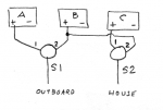
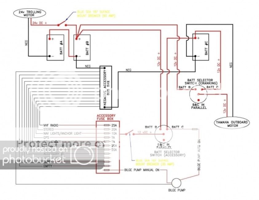
3 batteries in two "banks". Bank1 - starting. One battery. Bank2 - house. Two batteries.

Motor on Bank1 by default but able to pull from either or both in Bank2 if needed.

Accessories (everything else) on Bank2. 12v with the exception of a 24v trolling motor. 12v accessories should be able to pull from either battery in Bank2 and from the single in Bank1 if needed.

Trolling motor always pulls from Bank2. Never from Bank1.

I want the motor to charge at least the starting battery while under power. I would prefer it to charge all three.

The less i have to do manually, the better the world will be.

I did look through the stickies, but don't think i saw exactly what I'm describing. if someone could do a basic pencil drawing and post it, that would be a huge help.

Kevin
 
Last edited:

GKevinR

Seaman Apprentice
Joined
Aug 5, 2018
Messages
44
i modified this from a diagram i found that was almost what I want to do, but (per the text I'm including from the original poster), it is pretty manual and you have to set the two battery switches correctly to get the desired outcome. The one change i made to his/her design is that I wanted two batteries on the house - not the start - side, so keep that in mind reading the description of the way it works below.

If the design is sound, this is an option - but if there is a better way or a flaw in the design, I'd rather something not burst into flames...

*********************

THREE BATTERY

Here is another method of wiring three batteries to two loads. I refer to the batteries as A-B-C, and the loads as OUTBOARD and HOUSE. The only source of charging current is the OUTBOARD. There are two battery switches, S1 and S2. They are the usual OFF-1-BOTH-2 switches. All the negative terminals of the batteries are wired in common, but for clarity I do not show that in the sketch below:

Battery B can be connected to either the OUTBOARD or the HOUSE as an isolated battery, that is, without paralleling it with battery A or C. Battery A can also be isolated and connected to the OUTBOARD. Battery C can be isolated and connected to the HOUSE. For charging, we can charge one-at-a-time Battery A or Battery B from the OUTBOARD. To charge Battery C we must charge it in parallel with Battery B.

To manage all of this requires careful setting of the two battery switches, S1 and S2. There are many possible combinations of settings, which produce many resulting arrangements of batteries and loads being combined. This sounds good, but I tend to think of this system as being weak for just this reason--too much complexity. The operator has to keep a clear head and manage all the switch settings. With complicated settings possible, the opportunity to make a mistake is also present.

A sample of the many combinations possible:S1 set to 1
Battery A is connected to the OUTBOARD. S2 can be set as follows:

1 = Battery C to HOUSE; Battery B not connected
2 = Battery B to HOUSE; Battery C not connected
BOTH = Battery B and C are in parallel to HOUSE

The OUTBOARD runs from and charges Battery A. The HOUSE runs from either Battery B or Battery C or both, and there is no charging to either of them.

S1 set to 2
Battery B is connected to the OUTBOARD. S2 can be set as follows:

1 = Battery C to HOUSE; Battery A not connected
2 = Battery B to HOUSE (in parallel with OUTBOARD); Battery A not connected
BOTH = Battery B and C are in parallel and connected to both OUTBOARD and HOUSE, and are charging; Battery A not connected.

S1 set to BOTH
Battery A and Battery B are connected to the OUTBOARD and are being charged. S2 can set as follow:

1=Battery C to HOUSE; not being charged
2=Battery A and Battery B are in parallel and connected to both OUTBOARD and HOUSE, and are charging; Battery C not connected
BOTH=Battery A and Battery B and Battery C are in parallel and connected to both OUTBOARD and HOUSE, and are charging.
 

GKevinR

Seaman Apprentice
Joined
Aug 5, 2018
Messages
44
trying to upload a pic, but getting a PHP EXEC error no matter what I try. ???
 

alldodge

Moderator
Staff member
Joined
Mar 8, 2009
Messages
42,535
Yes the pic upload is not working, waiting on the site to fix
 

alldodge

Moderator
Staff member
Joined
Mar 8, 2009
Messages
42,535
The one issue which will not work is Bank 2 with series wiring to supply 24V to Trolling motor, can not be paralleled to provide 12V. The first bat in series can provide 12V for house circuits.

Bat A all good
Bat B good for house
Bat C only used in series with Bat B for 24V
 

GKevinR

Seaman Apprentice
Joined
Aug 5, 2018
Messages
44
this is what i had drawn out. then i found the other on another forum - it looks exactly like what I wanted. Anyone see anything questionnable about it? is there a better way to do it?
 

alldodge

Moderator
Staff member
Joined
Mar 8, 2009
Messages
42,535
No that will not work as your wanting
Left switch in position 2 will send 12V to Elect and 24V to troll
Left switch in position 1 will send 24V to Elect and 24V to troll
Left switch in position BOTH shorts House 1 bat and it blows up
 

alldodge

Moderator
Staff member
Joined
Mar 8, 2009
Messages
42,535
The more elaborate drawing will work

3_battery_wiring.jpg
 

GKevinR

Seaman Apprentice
Joined
Aug 5, 2018
Messages
44
I guess i can live without the instantaneous detonation option. I think I'll do the more elaborate drawing. :)

Thanks alldodge!
 

gm280

Supreme Mariner
Joined
Jun 26, 2011
Messages
14,605
Sounds like you need to design a PIC controller circuit (or a micro-controller) with some really heavy duty power MOSFETS as switches. It can be done, but is going to take a lot of clever wiring and programming to satisfy all your needs...JMHO
 

alldodge

Moderator
Staff member
Joined
Mar 8, 2009
Messages
42,535
The disconnect on the trolling motor can just be a plug, the other disconnect going to house circuits is not needed. When House is turned OFF this disconnects power. The House bat switch could also just be an ON/OFF.

I understand the need to parallel the Start with House Bat to start the motor. Don't understand why one would need to parallel the House with the Start just to run Electronics. Doing this can drain Start bat and may not be able to start the motor
 

GKevinR

Seaman Apprentice
Joined
Aug 5, 2018
Messages
44
i modified this from a diagram i found that was almost what I want to do, but (per the text I'm including from the original poster), it is pretty manual and you have to set the two battery switches correctly to get the desired outcome. The one change i made to his/her design is that I wanted two batteries on the house - not the start - side, so keep that in mind reading the description of the way it works below.

If the design is sound, this is an option - but if there is a better way or a flaw in the design, I'd rather something not burst into flames...

*********************

THREE BATTERY

Here is another method of wiring three batteries to two loads. I refer to the batteries as A-B-C, and the loads as OUTBOARD and HOUSE. The only source of charging current is the OUTBOARD. There are two battery switches, S1 and S2. They are the usual OFF-1-BOTH-2 switches. All the negative terminals of the batteries are wired in common, but for clarity I do not show that in the sketch below:

Battery B can be connected to either the OUTBOARD or the HOUSE as an isolated battery, that is, without paralleling it with battery A or C. Battery A can also be isolated and connected to the OUTBOARD. Battery C can be isolated and connected to the HOUSE. For charging, we can charge one-at-a-time Battery A or Battery B from the OUTBOARD. To charge Battery C we must charge it in parallel with Battery B.

To manage all of this requires careful setting of the two battery switches, S1 and S2. There are many possible combinations of settings, which produce many resulting arrangements of batteries and loads being combined. This sounds good, but I tend to think of this system as being weak for just this reason--too much complexity. The operator has to keep a clear head and manage all the switch settings. With complicated settings possible, the opportunity to make a mistake is also present.

A sample of the many combinations possible:S1 set to 1
Battery A is connected to the OUTBOARD. S2 can be set as follows:

1 = Battery C to HOUSE; Battery B not connected
2 = Battery B to HOUSE; Battery C not connected
BOTH = Battery B and C are in parallel to HOUSE

The OUTBOARD runs from and charges Battery A. The HOUSE runs from either Battery B or Battery C or both, and there is no charging to either of them.

S1 set to 2
Battery B is connected to the OUTBOARD. S2 can be set as follows:

1 = Battery C to HOUSE; Battery A not connected
2 = Battery B to HOUSE (in parallel with OUTBOARD); Battery A not connected
BOTH = Battery B and C are in parallel and connected to both OUTBOARD and HOUSE, and are charging; Battery A not connected.

S1 set to BOTH
Battery A and Battery B are connected to the OUTBOARD and are being charged. S2 can set as follow:

1=Battery C to HOUSE; not being charged
2=Battery A and Battery B are in parallel and connected to both OUTBOARD and HOUSE, and are charging; Battery C not connected
BOTH=Battery A and Battery B and Battery C are in parallel and connected to both OUTBOARD and HOUSE, and are charging.

ok, i'm continuing to think on the battery design as I do other stuff on the boat. take a look at the description above and the pic attached. I didnt do this design - i found it on a forum thread. this gets me *almost* everything I wanted including the ability to charge all 3 batteries from the alternator and the ability to back the starting battery with one or both of the house batteries. what is does not get me is 24v (using house batteries only) for a trolling motor.

Is there something i could add to this design to get 24v but not lose all the functionality described and attached?
 

Attachments

  • photo330141.png
    photo330141.png
    13.4 KB · Views: 1

alldodge

Moderator
Staff member
Joined
Mar 8, 2009
Messages
42,535
Is there something i could add to this design to get 24v but not lose all the functionality described and attached?

No


There is nothing that I can think of that will allow you to have 24V trolling motor connected and be able to charge all 3
 

alldodge

Moderator
Staff member
Joined
Mar 8, 2009
Messages
42,535
12 and 24 w ACR.jpg How about this
Run OB and Electronics from the start Bat. Use ACR so when motor is running the start and 1 of the Troll Bats is being charged.

Add a 2 bank charger so when plugged in it will charge all 3 Bats because ACR works both directions
 

GKevinR

Seaman Apprentice
Joined
Aug 5, 2018
Messages
44
im running so many accessories (bait tank, 2 sets of lights, fishfinder/gps/sonar, radio and speakers, etc) that I dont want to run electronics in any way that pulls from the start battery. i need to pull 12v accessories from one or both house batteries, but would also like to use them for 24v trolling motor. i could add another battery pair (making 5 batteries) but wanted to check and see if there was a more efficient way.
 

alldodge

Moderator
Staff member
Joined
Mar 8, 2009
Messages
42,535
In my pic, When you stop, shift bat switch from 1 (start bat) to 2 (rear house bat), now your using the rear house bat for electronics. When ready to go, shift back to 1 and fire the motor. As your running motor charges start and rear house.

Now if you only want to use the switch when needing to combine bats to start, then move electronics connection to rear house bat
 
Top