Bravo 3 engine installation / alignment

Steve51

Cadet
Joined
Sep 26, 2009
Messages
9
Hi wondered if anyone could help please.

Trying to install the engine and I believe am missing something.

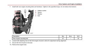
Everything was lined up and the rear mounting bolts all installed and located into the bottom nut.

The spacer is proud of the flywheel mounting fixing by some margin and there is a large gap under the washer – it just doesn’t look right.

I wondered if the spacer is “pressed” into the flywheel mounting fixing?

I have not tightened it up it up in case this was wrong!!

On top of that the alignment is way off (too low). Which I don’t understand, even by adjusting the mounting feet, unless the spacer is designed to lift the engine because the "gap" is about the same?

Unfortunately I had to let the yard crane go until another time when I am surer of the procedures.

Appreciate any pointers.

Thank you.
installation1.jpg
 

Scott06

Admiral
Joined
Apr 20, 2014
Messages
6,722
that is how it sits as shown in this thread- the spacer has to seat against the inner sleeve of the mount and not touch the flywheel cover so the rubber can act as an insulator against engine vibration.

https://forums.iboats.com/threads/mercruiser-rear-engine-mount-problems.700803/

Did you replace the gimbal bearing as well if so they need centering

can you post a pic of the witness marks on the alignment tool or is it too far off to get it in?

Are the rubber mounts in the flywheel cover collapsed? Do you have the older design with the spring and that is missing?
 

Steve51

Cadet
Joined
Sep 26, 2009
Messages
9
Hi, Just a follow up.. there is some confusion regarding a fibre washer and double wound lock-washer as one local engineer has mentioned.
These weren't in the install kit and no mention in the install manual.
 

Steve51

Cadet
Joined
Sep 26, 2009
Messages
9
that is how it sits as shown in this thread- the spacer has to seat against the inner sleeve of the mount and not touch the flywheel cover so the rubber can act as an insulator against engine vibration.

https://forums.iboats.com/threads/mercruiser-rear-engine-mount-problems.700803/

Did you replace the gimbal bearing as well if so they need centering

can you post a pic of the witness marks on the alignment tool or is it too far off to get it in?

Are the rubber mounts in the flywheel cover collapsed? Do you have the older design with the spring and that is missing?
Hi, thank you for your response. This is a completely brand new latest Bravo 3 install - and I haven't used the alignment tool yet as there doesn't appear any point at this stage as it looks too far off.
 

Steve51

Cadet
Joined
Sep 26, 2009
Messages
9
Also .. If I take the strain with the hoist off the engine and tighten down the bolt / washer onto the spacer I assume this will lift the engine?
Just didn't want to do that in case that was wrong.
 

Scott06

Admiral
Joined
Apr 20, 2014
Messages
6,722
Also .. If I take the strain with the hoist off the engine and tighten down the bolt / washer onto the spacer I assume this will lift the engine?
Just didn't want to do that in case that was wrong.
Not following here normally when installing an engine I put the back down & tighten the rear mounts. Then hang the front of the engine until the alignment is in the ballpark, its easier to adjust the side mounts this way. You may also have to move it side to side.

Is it possible you have issues with transom or stringer rot?
 

Steve51

Cadet
Joined
Sep 26, 2009
Messages
9
This is a complete new engine and sterndrive install including new transom stringers etc- all measurements accurately measured according to the drawings and I don't think that even maximum / minimum adjustment on the front motor mounts would raise the rear of the engine near enough and I would expect that installing on the inner transom mounts and mounting bolts all threaded should have been near enough. I will check again but it just seems so far out that I am missing something. I understand there is a shim kit but I didn't think I would need them.
I am surprised that the mounting bolts are proud and tall though it just doesn't look right
Thank you for your response.
 

Scott06

Admiral
Joined
Apr 20, 2014
Messages
6,722
This is a complete new engine and sterndrive install including new transom stringers etc- all measurements accurately measured according to the drawings and I don't think that even maximum / minimum adjustment on the front motor mounts would raise the rear of the engine near enough and I would expect that installing on the inner transom mounts and mounting bolts all threaded should have been near enough. I will check again but it just seems so far out that I am missing something. I understand there is a shim kit but I didn't think I would need them.
I am surprised that the mounting bolts are proud and tall though it just doesn't look right
Thank you for your response.
no its right with the bolts proud, again the sleeves are putting pressure only on the inner hub of the rear mount.

So the rear of the engine is too low? Drop the front mounts and the coupler should come up in relation to the gimbal bearing, it kind of works inverse to how you may think.
 

alldodge

Moderator
Staff member
Joined
Mar 8, 2009
Messages
42,535
I haven't used the alignment tool yet as there doesn't appear any point at this stage as it looks too far off.
Everything is NEW which means your looking through the gimbal bearing at the coupler. The gimbal bearing is most likely not 100% true to the coupler bore

Put the alignment bar in the bearing and move it around and then try to push it into the coupler to see how close you are
 

kenny nunez

Captain
Joined
Jun 20, 2017
Messages
3,325
If there is room under the engine get a small bottle jack under the harmonic balancer to raise or lower the engine.
 

Steve51

Cadet
Joined
Sep 26, 2009
Messages
9
What year is the boat?
Are you using the original bolt kit or a new kit that may had come with the new engine application?
Thank you.. that's interesting... Just to be clear this is a complete new engine and sterndrive package with rigging kit. The only difference from the drawing in the service bulletin is the fibre washer on the inner transom plate new design, has been replaced with a rubber moulding glued in place by Mercruiser.
I will double check over the next couple of days to check there is nothing that I have missed. It was just that the mounting bolt and washer standing proud, as I wasn't expecting that - so concentrating my efforts on a reason for that.
Thank you for all the responses.
 

dubs283

Vice Admiral
Joined
Jul 27, 2005
Messages
5,332
The design of the rear mounts changed about ten years ago and the pdf bulletin fun times posted does a thorough job of explaining installation and adjustment. The bulletin does, however "over explain" as they do at times because it covers most/all engine options from mercruiser

The easiest/broad stroke explanation I can give based on my experience is that first off you must ensure that both new engine mounts are fully seated in the flywheel housing prior to installation. I use a long bolt, washers, and nuts to "press" the mounts in place.

When you first install the engine package and release hoist tension with the rear mounts aligned and set on the inner transom plate mount seats you will be able to visually identify through the gimbal housing (looking fwd) if the coupler is aligned up/down with the gimbal bearing.

In your case it seems the coupler is below the line it needs to be for proper alignment. The new mount kit should have with it two washers/spacers that may or may not be needed. I would guess in your case they are needed. Remove the engine assy and place the washers/spacers on the inner transom plate mount seats and reinstall the engine package

Hopefully this will raise the aft end of the engine assy and you will see through visual confirmation (as described before) the coupler aligned up/down with the bearing and you can finish the alignment with the alignment bar/fwd mount adjustment
 

Steve51

Cadet
Joined
Sep 26, 2009
Messages
9
The design of the rear mounts changed about ten years ago and the pdf bulletin fun times posted does a thorough job of explaining installation and adjustment. The bulletin does, however "over explain" as they do at times because it covers most/all engine options from mercruiser

The easiest/broad stroke explanation I can give based on my experience is that first off you must ensure that both new engine mounts are fully seated in the flywheel housing prior to installation. I use a long bolt, washers, and nuts to "press" the mounts in place.

When you first install the engine package and release hoist tension with the rear mounts aligned and set on the inner transom plate mount seats you will be able to visually identify through the gimbal housing (looking fwd) if the coupler is aligned up/down with the gimbal bearing.

In your case it seems the coupler is below the line it needs to be for proper alignment. The new mount kit should have with it two washers/spacers that may or may not be needed. I would guess in your case they are needed. Remove the engine assy and place the washers/spacers on the inner transom plate mount seats and reinstall the engine package

Hopefully this will raise the aft end of the engine assy and you will see through visual confirmation (as described before) the coupler aligned up/down with the bearing and you can finish the alignment with the alignment bar/fwd mount adjustment
Hi, my guess is I need the shim kit (washers and spacers) as I am nearly at the bottom of the front mount adjustments . Still have a couple of turns but probably this would be necessary for final alignment.
Unfortunately the shim kit has to be ordered and here in the UK a long delay.
I can get a low profile jack at the rear of the engine and there is a bracket that would have been used if the engine was to be used with a shaft drive at that point.
I can obtain high quality fibre washers locally, so the plan would be to slacken off the mounting bolts, lift the engine to get a visual confirmation of the alignment. I can use a feeler gauge to measure the thickness, unless anyone can tell me the thickness of the shims in shim kit 12‑892619A01.
Thank you.
 

Scott06

Admiral
Joined
Apr 20, 2014
Messages
6,722
Hi, my guess is I need the shim kit (washers and spacers) as I am nearly at the bottom of the front mount adjustments . Still have a couple of turns but probably this would be necessary for final alignment.
Unfortunately the shim kit has to be ordered and here in the UK a long delay.
I can get a low profile jack at the rear of the engine and there is a bracket that would have been used if the engine was to be used with a shaft drive at that point.
I can obtain high quality fibre washers locally, so the plan would be to slacken off the mounting bolts, lift the engine to get a visual confirmation of the alignment. I can use a feeler gauge to measure the thickness, unless anyone can tell me the thickness of the shims in shim kit 12‑892619A01.
Thank you.
I think on last page (in 2nd column of chart) of attached service bulletin it says "2.7 mm thickness Spacer".

Have never seen the kit but looks like it is just a thick fiber with additional metal washer https://www.amazon.com/Mercury-quicksilver-12-892619A01-Shim-Kit/dp/B007D2NAUK
 

Steve51

Cadet
Joined
Sep 26, 2009
Messages
9
Hi, just an update on this if I may.

I ended up making a gantry over the engine and used a 1 ton chain hoist and lifting strap. This gave me plenty of time to adjust the position of the hoist to suit, as I only needed to raise a few millimetres.

I raised it just enough to get the coupler near enough then checked the engine was level and bolt down the rear bolts on the transom plate. I then adjusted the engine mounts to suit, torque up the rear bolts and released the tension on the hoist. This now looks a lot better and just maybe slight adjustment of the front mounts for the alignment.

I still have to bolt down the front mounting feet but I need to check the engine is square, which I will do with a 1 inch tube / rod before drilling holes in the bearer and then use the alignment tool.

I have ordered the shim kit just in case as there is a long delay in the UK. The shims look special and it is difficult just to buy fibre washers and stainless steel washers without knowing the diameters.

Thank you for your help.
 
Top