Romeo21779
Cadet
- Joined
- Dec 12, 2008
- Messages
- 20
First, I'd like to apologize about the length of this post...
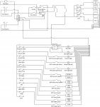
The wiring on our 1991 Rinker 260 Fiesta Vee is a huge disaster at this point and we would like to clean it up. The boat has a Mercuiser 454 with a Bravo 1. The boat was bought used. While the engine and drive are in good working the order the same cannot be said for the wiring. The plan is to replace the battery charger with something that was made this decade, get rid of the isolator and switch to a VSR and just generally clean up wiring so that we know where all of it goes. I don't think I saw a ground bus anywhere in the engine bay, I think everything just grounds to the engine right now.
At this point, there are switches on the dash that do absolutely nothing. The glass fuses are getting really annoying and I'd like to replace the panels with automotive style fuses. We'll probably get a blue seas 12 circuit and blue seas 6 circuit fuse panels, both with ground bus bar built in.
The first version of my wiring diagram is attached and the following questions are based off of it.
1. Am I correct in thinking that the Trim tab pump, drive trim pump, blower and horn should receive power from the starting battery or do they get their power from the ignition switch?
2. Can I mount the that fuse panel in the engine bay as opposed to running 4 gauge wire all the way to helm and then running wire back to the pumps. Should I just run the horn off of the accessory panel or am I okay with just running a power lead for the horn from the engine bay? Accessory panel will be mounted at the helm.
3. Do you guys think I should have a switch for the cabin lights since each fixture has its own switch?
4. Should I include switches for the accessory socket, VHF, or the stereo?
5. I want switches for the chartplotter and NMEA2000 just in case I have to do a hard reset. Easier to flick a switch than disconnect power from it since it will flush mounted this winter when the dashboard is redone.
6. I want to have a switch for the fridge even though it has its own switch inside the fridge. I'd like to be able to control it from the helm instead of having to go below to make sure that its off if I don't want to drain the battery. Good/bad idea?
7. The battery switch/VSR cluster is based off the BEP marine cluster. Any glaring mistakes in that?
8. Do I have the correct understanding that the only connection to the engine wiring I need to make goes the alternator? I have the service manual for the engine and based on those diagrams, that is my understanding but I just want to make sure. I don't want to touch the engine wiring just yet as it all works as of now but I will replace the connectors and if the wire is all corroded I will end up redoing the engine harness as well.
9. Am I okay to use 4gauge from the circuit breakers to the fuse panels? What size circuit breakers do I need?
10. I will most likely use 0 gauge from the alternator to the battery switches and from the switches to the batteries. Overkill or okay?
11. What gauge wiring should I use for the trim tab pump and drive trim pump?
I think that is it for now. Thank you to everyone who actually read the entire post. If you need any clarification on anything, please ask.
And thanks in advance for any advice.