DVA adapter vs DVA analog meter for sensor and coil wire testing

gilera

Seaman
Joined
Aug 29, 2021
Messages
58
Hi,
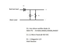
I have a few 1970's V4 crossflows. Part of the ignition troubleshooting is to measure the output from sensor wires to gnd and orange coil wires to gnd. These are supposed to be 150V. I have never got this to work using my homemade DVA adapter. It seems to work fine for stator measurement and the sensor signal across sensor wires 1 to 3 and 2 to 4.

Last week I bit the bullet and bought a ESI DVA adapter. I was disappointed to find that it seems no better than my homemade one for these measurements. It basically gets to like 1 or 2 volts reading (and takes a while to even get this high) where it should be 150V plus. I am thinking that this may be due to the intermittent nature of these signals in a 4 cylinder motor. Presumably this would be even more challenging on a 6 cylinder.

Has anyone else had difficulty with these measurements?

Does anyone know if the ESI analog meter with DVA function capture these signals better?

I have read that they work better for the low voltage signal across the sensor wires due to not having the voltage drop associated with the diode in a DVA adapter which can give misleadingly low reading but I have no issue with this.

I don't want to fork out for another device if it will also have the same issue.
 

Crosbyman

Vice Admiral
Joined
Nov 5, 2006
Messages
5,648
dva adapter are just simple AC to DC rectifiers with a capacitor to help build up a peak DC voltage derived by storing the peaks of the AC signal .

if both your DVA and the ESI version give the same results the problem is likley not the DVA adapters. Hoefully your meter is set to DC !

there are several schematics on the Net for you to try out.

here is a simple one and CDI info
 

Attachments

  • dvacircuit.jpg
    dvacircuit.jpg
    27.6 KB · Views: 6
Last edited:

gilera

Seaman
Joined
Aug 29, 2021
Messages
58
dva adapter are just simple AC to DC rectifiers with a capacitor to help build up a peak DC voltage derived by storing the peaks of the AC signal .

if both your DVA and the ESI version give the same results the problem is likley not the DVA adapters. Hoefully your meter is set to DC !

there are several schematics on the Net for you to try out.

here is a simple one and CDI info
Yes that is the schematic I used and yes on DC. It works fine where there is constant voltage e.g. stator. I even tried removing the first resistor. This did help and I was able to get the voltage reading up to about 18V but still no where near what it should be. I suspect that it is the duty cycle of the signal on a multi-cylinder engine. It is just not there enough to build up in the capacitor.

I'm yet to hear of someone saying that they have been able to measure these readings on one of these engines using a DVA adaptor even though the CDI troubleshooting guide says to do it.
 

gilera

Seaman
Joined
Aug 29, 2021
Messages
58
Interesting that on the CDI chart you linked to under my motor (85-140hp 1973-1977) it just says N/A under power coil as in there are no DVA measurements. The CDI troubleshooting guide calls for these various measurements under the same motor:
Annotation 2023-12-06 122509.png

Annotation 2023-12-06 122630.png

Annotation 2023-12-06 1226301.png

I feel like some of these have been cut and pasted from other motors. For example the coils on these motors have the orange wire permanently attached, not removable like the later style coil on the twin powerpack motors. Yet the guide says to "Disconnect the Orange wire from the ignition coil".
 

Faztbullet

Supreme Mariner
Joined
Mar 2, 2008
Messages
15,930
it just says N/A under power coil as in there are no DVA measurements.
Dont know where you got the spec but here is the correct ones..
1701828886631.png
 

Attachments

  • 1701828768740.png
    1701828768740.png
    80.7 KB · Views: 2
Last edited:

gilera

Seaman
Joined
Aug 29, 2021
Messages
58
But isn't that what testing the orange wire is all about? I guess technically it is the signal going to the coil you are measuring rather than the coil itself but test with and without the orange wire connected to the pack is used to identify if the coil is bad.
Oh it is talking about the stator, not the ignition coil isn't it. My mistake.
 

gilera

Seaman
Joined
Aug 29, 2021
Messages
58
Are you looking up a different motor to mine? I get this straight from the 7th edition CDI troubleshooting guide from the CDI website.

Annotation 2023-12-06 1322202.png
 
Last edited:

gilera

Seaman
Joined
Aug 29, 2021
Messages
58
Is it just me or does the spec sheet that Faztbullet posted have an error? The table shows that Black/White to gnd should be 0.6V, but then point 9 says it should be at least 150V.
 

Scott Danforth

Grumpy Vintage Moderator still playing with boats
Staff member
Joined
Jul 23, 2011
Messages
50,230
what brand of DVA are you running? even my 25 year old Fluke with auto sense or the free ones from harbor freight work fine for troubleshooting without any adapter.
 

dingbat

Supreme Mariner
Joined
Nov 20, 2001
Messages
16,313
The table shows that Black/White to gnd should be 0.6V, but then point 9 says it should be at least 150V.
Sounds like you’re confused as to what is going on.

You’re dealing with a capacitor discharge system. Voltage is built up in a capacitor then collapsed (discharged) and the process starts over again.

As such, you’re dealing with pulsed AC similar to the trace shown below.

Note the duration of each peak collapse cycle. It’s these peaks, and only these peaks you’re trying to capture with a DVA.

Your 150V is the peak AC output on the “supply” side.

The 0.6V is mostly rectified DC (with a bit of AC in the trace) after filtering


IMG_3038.png
 

Crosbyman

Vice Admiral
Joined
Nov 5, 2006
Messages
5,648
DVA adapters allow you to accumulate peaks of AC in a capacitor after they are "line up" or rectified by the diode. Most meters can't catch the peaks so storing them in a capacitor as DC allows their measurement.

common houseold AC around 120 volts actually has peaks much higher peaks we don't bother with .

These peaks becomes evident in voltage doubler circuits easly built to test outboard capacitors. When charged up and rectified 120V AC becomes 340 DC with both half cycles peaks added up together before storage.
1701875689624.png

Since most of us do not use or have ever used an oscilloscope the single diode DVA just takes one AC cycle peak and piles it up in a capacitor because the capacitor can "store" DC for easy reading with a common VOM .
 
Last edited:

gilera

Seaman
Joined
Aug 29, 2021
Messages
58
Sounds like you’re confused as to what is going on.

You’re dealing with a capacitor discharge system. Voltage is built up in a capacitor then collapsed (discharged) and the process starts over again.

As such, you’re dealing with pulsed AC similar to the trace shown below.

Note the duration of each peak collapse cycle. It’s these peaks, and only these peaks you’re trying to capture with a DVA.

Your 150V is the peak AC output on the “supply” side.

The 0.6V is mostly rectified DC (with a bit of AC in the trace) after filtering


View attachment 392404
But wouldn't each cylinder (each sensor wire) be betting the signal less frequently with each additional cylinder. For example would a single cylinder motor running at 5000rpm be getting a much more frequent spark on its one plug compared to each plug on a 4 cylinder motor running at the same RPM? I am wondering if this is affecting the ability of the capacitor to accumulate charge.
 
Top