Electronic ignition Delco Est

SSTKO81

Petty Officer 1st Class
Joined
Jun 1, 2009
Messages
344
Good afternoon boys and girls! The time has come to replace my distributor (worn bushings) and rather than just replace ive decided to upgrade. I purchased a gently used electronic distributor that I thought would come with the wiring harness and coil, but it did not... No biggie, I can make my own in just an hour’s time, but can this distributor be used with a traditional style ignition coil? I ditched the factory on and the resistor wire some time ago, so I’ve got a full 12v to the coils (if that makes a difference.... anyone done this? In theory it should work but didn’t know if I was maybe missing something....
 

SSTKO81

Petty Officer 1st Class
Joined
Jun 1, 2009
Messages
344
Thanks


Yes, there is no need for external resistor wire as needed with points. Needs full 12V during starting and while running

Thank you!
Do you know if a traditional coil can be used or will I have to go find a new coil pack?
 

alldodge

Moderator
Staff member
Joined
Mar 8, 2009
Messages
42,537
Get another coil unless its labeled internal resistance

Points used external resistance, electronic used internal
 

Scott Danforth

Grumpy Vintage Moderator still playing with boats
Staff member
Joined
Jul 23, 2011
Messages
50,230
you can run a ballast resistor with the coil if needed. internal resistance coil = external resistance coil with ballast just make sure the ballast resistor plus coil match the specs of the EST 9voyager) dizzy. the dizzy does need full 12 volts to the ICM
 

achris

More fish than mountain goat
Joined
May 19, 2004
Messages
27,468
Where did you get the new distributor?
 

SSTKO81

Petty Officer 1st Class
Joined
Jun 1, 2009
Messages
344
you can run a ballast resistor with the coil if needed. internal resistance coil = external resistance coil with ballast just make sure the ballast resistor plus coil match the specs of the EST 9voyager) dizzy. the dizzy does need full 12 volts to the ICM

im using a flame thrower coil -pretty sure it’s internal resistance
 

SSTKO81

Petty Officer 1st Class
Joined
Jun 1, 2009
Messages
344
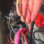
I am wiring up my new distributor with a new correct coil and the harnesses that I was able to find an salvage yard. I have run into a snag directions indicate that there should be ignition side to the coil and a positive side… It looks like the positive side should be coming from this red wire in lieu of the resistor wire. But there is another wire that is purple with a yellow stripe coming off the starter that was also on the old coil does anyone know if this is also supposed to be run to the ignition side of my coil?
 

Attachments

  • photo329287.jpg
    photo329287.jpg
    1.6 MB · Views: 0

alldodge

Moderator
Staff member
Joined
Mar 8, 2009
Messages
42,537
Ignition is purple
Start circuit to bypass is purple/yellow
Red is 12V full time

Your points would have a feed from a purple/yellow coming from the starter during cranking (connected to + side of coil).

Once motor started 12V would go thru the purple wire from key switch to a splice, which connected to a purple resistance wire connecting to + side of coil

You need to find what turns ON/OFF with the key. Then trace the original resistance wire going to coil back where it was spliced, and run regular wire to + side of coil
 

SSTKO81

Petty Officer 1st Class
Joined
Jun 1, 2009
Messages
344
Ignition is purple
Start circuit to bypass is purple/yellow
Red is 12V full time

Your points would have a feed from a purple/yellow coming from the starter during cranking (connected to + side of coil).

Once motor started 12V would go thru the purple wire from key switch to a splice, which connected to a purple resistance wire connecting to + side of coil

You need to find what turns ON/OFF with the key. Then trace the original resistance wire going to coil back where it was spliced, and run regular wire to + side of coil

I think you answered my question. Since there are no more points there is no more need for the purple and yellow wire, it would be redundant. So I can simply go off the red wire that now takes the place of the original purple resistance wire. That’s in line with what I was thinking.... We couldn’t possibly both be wrong! LOL👍🏼
 

SSTKO81

Petty Officer 1st Class
Joined
Jun 1, 2009
Messages
344
Also, I assume it will be necessary to wire in a bypass to the dizzy thru the shift interrupt switch; correct ?
 

SSTKO81

Petty Officer 1st Class
Joined
Jun 1, 2009
Messages
344
What of the grey and black wires already running to the switch?
 

alldodge

Moderator
Staff member
Joined
Mar 8, 2009
Messages
42,537
What of the grey and black wires already running to the switch?

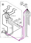
Oh, yes you have to change those. The points distributor use a ground to cause the spark to die in order to shift.

The EST uses 12V to the dizzy to do the same thing. Take ignition power (purple) to one side

ALSO my bad, but you need another coil, one of the HEI styles like in the drawing above. Search delco est coil and use who's ever
 

SSTKO81

Petty Officer 1st Class
Joined
Jun 1, 2009
Messages
344
I went ahead and picked up an appropriate coil and pigtails at the local salvage 👍🏼. I’ve got all that wired in with the exception of the shift interrupt. -sound like I’ll just run a wire from the distributor to the switch and then From the switch to ground? And the grey wires running to the switch can just be lift disconnected if I’m understanding.
Thank you for all your help
 

SSTKO81

Petty Officer 1st Class
Joined
Jun 1, 2009
Messages
344
I went back and looked again at your diagram, I now see that the wire would go purple to switch to dizzy. Gotcha! And the great and black wires would just terminate.
 
Top