I have a weird problem I'm hoping someone can help me with.
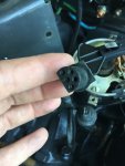
I have a 1988 OMC King Cobra 5.7L. The model number is 574PBRGDP. The ESA module I took off has part # 987571 written on it which is for an engine with a BID (Breakerless Ignition Distributor) made by Pertronix. Problem is my engine has a points style distributor made by Mallory. The distributor is original (I bought the boat new in 1989). The module may have been replaced.
The instruction sheet that came with the new module says NOT to use it with points style ignition. The module that the parts book says to use does not have the same plug connector, in fact it has 2 connectors (my original has 1- 5 wire plug).
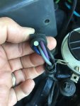
The instruction sheet said to check the resistance on the gray/black wire on the engine side of the ESA connector but the connector on my boat only has 4 wires coming out. The engine side pin location for the gray/black wire on the ESA side has a plug in it. Again, factory.
Also, I cannot find a ballast resistor so I’m assuming there is a resistor wire there but I’ve not had a chance to check the resistance.
So my question is has anyone seen this mix of parts? Any wire diagram that shows this combo?
Thanks,
I have a 1988 OMC King Cobra 5.7L. The model number is 574PBRGDP. The ESA module I took off has part # 987571 written on it which is for an engine with a BID (Breakerless Ignition Distributor) made by Pertronix. Problem is my engine has a points style distributor made by Mallory. The distributor is original (I bought the boat new in 1989). The module may have been replaced.
The instruction sheet that came with the new module says NOT to use it with points style ignition. The module that the parts book says to use does not have the same plug connector, in fact it has 2 connectors (my original has 1- 5 wire plug).
The instruction sheet said to check the resistance on the gray/black wire on the engine side of the ESA connector but the connector on my boat only has 4 wires coming out. The engine side pin location for the gray/black wire on the ESA side has a plug in it. Again, factory.
Also, I cannot find a ballast resistor so I’m assuming there is a resistor wire there but I’ve not had a chance to check the resistance.
So my question is has anyone seen this mix of parts? Any wire diagram that shows this combo?
Thanks,