Evenrude Lark 6 "Selectric shift" Generator not charging.

areoseek

Seaman Apprentice
Joined
Jun 27, 2015
Messages
49
I have a late 60's lark 40hp. I was told it has to be a 67 because it's seletric shift with a generator. (F,N,R).


I'm getting ready for the 2016 fishing season and would like her to keep the starting battery charged up.

I've got a good belt, and good fuses in the little wiring box, but According to my multimeter, no incoming current. Battery stays right at 12.5 when she's running and 12.4 when she's in gear. (obviously this goes down as the battery dies).


I was told something about "polarizing the generator", but am unsure what or how to do that.

I have somewhat more than basic electrical knowledge from working on cars for a living, but I've always delt with alternators.


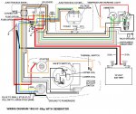
There is what appears to be a voltage regulator in the grey junction box, with a few glass tube fuses.

What kind of voltage should this puppy put out? I expecting less than 5 amps, but even that would be able to recharge her after just running the fish finder for a while.


Any and all input is appreciated. Thanks!.
 

racerone

Supreme Mariner
Joined
Dec 28, 2013
Messages
38,422
NO---The electric shift was made from 1962 to 1970.-----Puts out a maximum of 10 amps.-----Yes try the polarizing first.-----I think google will know the procedure for that.----Haven't done one myself for a while now.
 

F_R

Supreme Mariner
Joined
Jul 7, 2006
Messages
28,226
First, you need to know that it doesn't charge at all until you get it up to about 1500-2000 RPM. Then the relay contacts close and it will put out a max of 10 Amps and the voltage is regulated.. Some people like to point out that isn't much. But hey, many/most unregulated alternators put out only 5-6 Amps.

Trouble is, there aren't many of us old timers around that understand how it works, or how to troubleshoot it. I could spend a lot of time typing, but better you break down and buy a factory service manual.

To bench test and polarize a generator (of this type):
Remove belt
Remove wires from bottom end.
Make sure motor (or generator housing if removed from motor) is grounded to battery (-)
Also ground the Field terminal on gen (the small one)
Use a jumper wire to connect battery (+) to Armature terminal on gen (the larger one)
Connected as just described, the generator should run slowly like a motor. (This also polarizes it)

BTW, it is important that the generator works. A discharged battery can severely damage the electric clutches.
 
Last edited:

F_R

Supreme Mariner
Joined
Jul 7, 2006
Messages
28,226
Has the boat got an amp meter on it ??


Of course boobie knows this, but he has a point. The boat is supposed to have an amp meter. That tells at a glance if the system is working or not. Makes troubleshooting a lot easier too. But of course the possibility is there that the meter is missing. Then right away the question becomes is it wired correctly? Charging current goes through that amp meter.
 

areoseek

Seaman Apprentice
Joined
Jun 27, 2015
Messages
49
Of course boobie knows this, but he has a point. The boat is supposed to have an amp meter. That tells at a glance if the system is working or not. Makes troubleshooting a lot easier too. But of course the possibility is there that the meter is missing. Then right away the question becomes is it wired correctly? Charging current goes through that amp meter.

no ammeter. only spedo. I have a clamp on one I can try. Which wire should I test from? I'm going to pull off the genny and bench test it as described above as soon as it warms up again. Non stop snow plowing right now. Thanks for the continued help guys.
 

racerone

Supreme Mariner
Joined
Dec 28, 2013
Messages
38,422
Are the first 3 numbers 407 in your model # ??----Do you have most of the wiring harness.----Does it come with the big junction box that mounts inside the boat ?
 

F_R

Supreme Mariner
Joined
Jul 7, 2006
Messages
28,226
No Title

racerone is speculating you may have a 1967 or newer, where the junction box was eliminated. Because of your OP mentioning the glass fuses, I assumed you have the junction box.
If you follow the regulator output (brown wire) you will see that it leads to the ammeter, then the green wire takes it back to the starter solenoid/battery + cable. My point was that the regulator output must be connected to the battery + (normally done as I just described).

EDIT: Note that a careful look at the diagram shows that the brown generator - to - ammeter wire does not pass through the 20A fuse. The fuse is for the power take-off terminal on the bottom of the box.

EDIT EDIT: The diagram is for a standard shift motor. Therefor the electric shift wires aren't shown. But the rest of the wiring is the same.
 

Attachments

  • photo238101.jpg
    photo238101.jpg
    184.2 KB · Views: 0
Last edited:

boobie

Supreme Mariner
Joined
Nov 5, 2009
Messages
20,826
On these generator systems if your battery isn't getting charged and you have no amp meter put a volt meter across the battery and connect a jumper wire from the field terminal on the regulator to ground. Run the motor around 2000 rpm. If the voltage goes up your generator is okay and the problem is in the regulator or the wiring.
 

areoseek

Seaman Apprentice
Joined
Jun 27, 2015
Messages
49
racerone is speculating you may have a 1967 or newer, where the junction box was eliminated. Because of your OP mentioning the glass fuses, I assumed you have the junction box.
If you follow the regulator output (brown wire) you will see that it leads to the ammeter, then the green wire takes it back to the starter solenoid/battery + cable. My point was that the regulator output must be connected to the battery + (normally done as I just described).

EDIT: Note that a careful look at the diagram shows that the brown generator - to - ammeter wire does not pass through the 20A fuse. The fuse is for the power take-off terminal on the bottom of the box.

EDIT EDIT: The diagram is for a standard shift motor. Therefor the electric shift wires aren't shown. But the rest of the wiring is the same.


I DO have a junction box. I DO NOT know the model number. I DO have the complete wiring harness, however mangled by the p/o attempting to do dual batteries and hardwire accessories. Where can I find the model number on this bad girl? I will take pictures of everything when I get home from work this evening.


Edit: looking at that schematic, it looks like I'm supposted to have a tach and a temp warning light as well. interesting. I also don't have a "kill switch". I have to choke the motor out to turn it off.
 
Last edited:

racerone

Supreme Mariner
Joined
Dec 28, 2013
Messages
38,422
It would be best to avoid running the motor untill you have things sorted out and wired correctly.--Big $$$ could be wasted with shoddy wiring !
 

areoseek

Seaman Apprentice
Joined
Jun 27, 2015
Messages
49
some pictures for reference on what i'm dealing with.
2wmjhqo.jpg

1zwcen9.jpg

29e3pd0.jpg

zwj3on.jpg

jf7lue.jpg


Still haven't worked on the generator. sorry. started restoring it while I have a free garage bay
 

F_R

Supreme Mariner
Joined
Jul 7, 2006
Messages
28,226
The tachometer wire is there for just in case the customer buys the optional accessory tach. Not a necessary item at all. The key switch is the kill switch
 

areoseek

Seaman Apprentice
Joined
Jun 27, 2015
Messages
49
The tachometer wire is there for just in case the customer buys the optional accessory tach. Not a necessary item at all. The key switch is the kill switch
Thank you!

from reading the diagram, it shows a thermal switch. Does that mean If I overheat she'll shut herself down?
 
Last edited:

F_R

Supreme Mariner
Joined
Jul 7, 2006
Messages
28,226
No!! The thermal switch turns on the overheat warning light---that's all.
 

areoseek

Seaman Apprentice
Joined
Jun 27, 2015
Messages
49
No!! The thermal switch turns on the overheat warning light---that's all.
i'll have to find her and install a light. that'll be nice to have in case I clog the impeller pickup or something.
 
Top