Ground fault with black wire melting

Earl D

Cadet
Joined
Mar 15, 2023
Messages
20
Just acquired 1989 Bass Tracker Tournament TXS. Previous owner had trickle charger installed for two trolling batteries and a starting starting. I couldn't get a clear picture of what happened but prior owner stated that when the boat was returned to him, there was a red wire loose in the rear compartment where the starting motor is located. He 'dropped' the wire onto the positive post of the starting battery and wires began to melt, especially ground wires. My problem is two fold. Apparently there are no wiring diagrams out there for Bass Tracker which leaves me in the dark. And second, the wiring running from the console to the back compartment runs under the rear deck and there is no way to see what is going on with the wiring. I can speculate all day long about what is going on with melted ground wires but 'short' keeps popping into my head. I would appreciate any guidance/recommendations on how to find out what is melting wires.
 

alldodge

Moderator
Staff member
Joined
Mar 8, 2009
Messages
42,567
Agree there is a short
Might get some strong nylon string/cord and tie to end of wires, then pull wires out other end. The cord will allow new wires to be pulled back thru
 

Earl D

Cadet
Joined
Mar 15, 2023
Messages
20
Agree there is a short
Might get some strong nylon string/cord and tie to end of wires, then pull wires out other end. The cord will allow new wires to be pulled back thru
There is apparently a splice in the ground wire somewhere under the rear deck. I have confirmed that one ground wire runs from the front nav light, through the console, under the rear deck and out into the rear compartment. The end of that ground wire as well as another ground wire (which comes from under the rear deck) are both burnt with the insulation melted. I have tried to pull the long ground back into the cockpit area and it will not come. I think a splice is preventing it from coming out from under the rear deck.
 

Earl D

Cadet
Joined
Mar 15, 2023
Messages
20
With a boat next to nothing is every easy
This being my first bass boat, I am considering cutting through the aluminum on the starboard end of the back compartment to gain, hopefully, access to the wiring running through that area. Once wiring is completed I will attach the cutout panel back in place with pop rivets. Do you see any drawbacks to doing that?

Stop the circus: There are two outside vent covers on the stern of the boat. I removed the starboard cover and I found there is access to the wiring. The wiring runs through 4" pvc from the cockpit to the rear of the boat. It then dumps out into an area under the vent cover. I now just have to play with the wiring to find out where the short is.

Thanks for the help.
 
Last edited:

Earl D

Cadet
Joined
Mar 15, 2023
Messages
20
This being my first bass boat, I am considering cutting through the aluminum on the starboard end of the back compartment to gain, hopefully, access to the wiring running through that area. Once wiring is completed I will attach the cutout panel back in place with pop rivets. Do you see any drawbacks to doing that?

Stop the circus: There are two outside vent covers on the stern of the boat. I removed the starboard cover and I found there is access to the wiring. The wiring runs through 4" pvc from the cockpit to the rear of the boat. It then dumps out into an area under the vent cover. I now just have to play with the wiring to find out where the short is.

Thanks for the help.
I'm posting this in case someone in the future runs into what a mess I found. I should clarify that to gain access to the wires under the vent cover, the hose (4") from the back compartment to the vent would have to be removed. In the case of this boat, someone removed the the hose at some point so I didn't have to remove it from the vent to gain access. After looking at the wiring, I think someone at some point did a horrible job of rewiring the boat. Nothing that was done makes any sense to me. Since wires were melted I'm not sure what the connections were but there were two wires inside the back compartment that had the insulation on the wires melted. One black wire that was melted went to a shrink wrap connector with two black wires coming out of the back side of the connector. The other black wire (the single black wire) that had the insulation melted went to a metal crimp connector. That metal crimp connector had the two wires from the shrink wrap connector plus the single black wire going into one end of the metal crimp connector. The black wire coming out of the other end of the metal connector was the ground for the console and ran from the back of the boat up and into the console.

There is a fuse block under the console which powers the nav lights, the bilge, aerator and a number of other components. None of those fuses were blown, probably because none of them were turned on when the short took place.

Since the console is powered off the starting battery, the console being the instrument lights, the nav lights, live well, the rpm, water psi, flasher, voltage, and mph gauges it seems to me that all would be grounded by a single wire going to a fuse block in the rear compartment of the boat. That fuse block would be grounded by one single wire coming from the battery. Some way or other, two ground wires got involved in grounding inside the back compartment. Don't have a clue why.

There is a bilge pump, aerator pump and bilge float inside the back compartment. I would run ground from them to a fuse block, just as the console gauges, with again one single ground coming from the battery. Again, why did the system that melted have to melted ground wire.

The melted wires ended at the metal crimp where all of the ground wires were crimped together. The ground running to the console from the metal crimp is fine.

I realize this is probably rambling but any comments would be appreciated.
 

dingbat

Supreme Mariner
Joined
Nov 20, 2001
Messages
16,317
Never assume when it comes to wire colors.

The fact that it melted when connected to ground tells you the wire has potential, in other words it’s hot.

Remove the suspect wire at both ends. Test for continuity between both the ends of the wire.

If that checks out, check continuity between battery ground and a known hot supply to determine if it’s a hot or ground connection. If it rings to both (+ and -) you have a dead short

Very well could be the float/bilge pump wiring. Fairly common for a bilge pump to fail shorting hot to ground.
 

Earl D

Cadet
Joined
Mar 15, 2023
Messages
20
Never assume when it comes to wire colors.

The fact that it melted when connected to ground tells you the wire has potential, in other words it’s hot.

Remove the suspect wire at both ends. Test for continuity between both the ends of the wire.

If that checks out, check continuity between battery ground and a known hot supply to determine if it’s a hot or ground connection. If it rings to both (+ and -) you have a dead short

Very well could be the float/bilge pump wiring. Fairly common for a bilge pump to fail shorting hot to ground.
I have checked the continuity of the ground wire which runs from the back of the rear deck to the console. That continuity is good.

I'm a novice at this and I am not sure what you mean by check continuity between battery ground and a known hot supply to determine if it's a hot or ground connection. If I understand what I would need to do is have a battery ground come off the battery and connect with the ground wire (-) that runs from the rear deck up to the console. And then, have a wire (+) running from the battery positive up to the console. If I check the continuity of those two wires at the console, I should not have continuity. If I do then that (+) wire is a problem? I would do this check with every (+) wire on the boat?

What will the voltmeter do or show with a hot connection? What will it do with a ground connection?
 

dingbat

Supreme Mariner
Joined
Nov 20, 2001
Messages
16,317
I'm a novice at this and I am not sure what you mean by check continuity between battery ground and and know hot supply to determine if it's a hot or ground connection.
First, are you sure the battery charger is wired correctly? Remove the charger from the situation to see what happens

Remove power and ground connections from all batteries to isolate the wiring from power.

Measure continuity between the “suspect” wire and each of the battery leads. Should not have continuity at any of the positive leads.
Should have continuity between all three ground cables.
What will the voltmeter do or show with a hot connection? What will it do with a ground connection?
It’s not going to tell you anything unless current is flowing. Your meter probably wouldn’t take it well ;)

What you have now is a wire with an unknown potential. You think it’s a ground, but grounds don’t burn grounds when connected.

The grounds melting would require a large volume of current. Would need to be a dead short to a battery or AC coming in on the charger power cord. Shouldn’t be hard to find. Start with the obvious
 

Earl D

Cadet
Joined
Mar 15, 2023
Messages
20
First, are you sure the battery charger is wired correctly? Remove the charger from the situation to see what happens

Remove power and ground connections from all batteries to isolate the wiring from power.

Measure continuity between the “suspect” wire and each of the battery leads. Should not have continuity at any of the positive leads.
Should have continuity between all three ground cables.

It’s not going to tell you anything unless current is flowing. Your meter probably wouldn’t take it well ;)

What you have now is a wire with an unknown potential. You think it’s a ground, but grounds don’t burn grounds when connected.

The grounds melting would require a large volume of current. Would need to be a dead short to a battery or AC coming in on the charger power cord. Shouldn’t be hard to find. Start with the obvious
First a question. Am I correct in thinking that if a component, for example the bilge pump, has a (-) and (+) wire coming from the battery and the (+) wire was someway compromised and the (+) wire metal is touching the (-) wire metal that a dead short is created and the (-) wire would melt? In this case I would get continuity if I probed one end of the (-) wire and the other end of the (+) wire?

When I got the boat there was no wires connected to the starter battery and the ground that did go to the battery had all of the insulation burnt off and was laying in the back compartment. For some reason the (+) red wire which had gone to the battery was cut and laying in the back compartment.

I have made no attempt to reconnect any original wires to the starter battery. I did connect a 3 bank trickle charger to two trolling batteries and the starter battery. There was no sparking when I made the connections and the charger leds indicated that it was working correctly.

Since the ground wires (2) were a burnt mess and there was no way to ascertain what was going on with the ground wires, I disconnected all components, the bilge pump, aerator, console, bilge pump float, etc., from the electrical system. In reality, the boats electrical system right now consists of the trickle charger circuit and the wiring that runs to the trolling motor which is not currently connected to the motor.

All electrical components, bilge pump, aerator, etc., are fused under the console. None of the fuses were blown. The instruments, which I doubt even work, are not fused and were part of the electrical system.

I am thinking about running a (-) and (+) wire from the battery to a fuse block in the back compartment. Then connecting each component, bilge pump, etc., to the fuse block, one component at a time. Of course the wiring will have to run from the back compartment up to the console bilge switch and back to the fuse block. If I don't experience a wire melt down I could assume the problem has been corrected?
 

Earl D

Cadet
Joined
Mar 15, 2023
Messages
20
My problem appears to be a short circuit and I found this rather descriptive method of testing for a short circuit. " To find a short, look for continuity where it should 'not exist.' Disconnect the circuit from the battery and disconnect the equipment from the circuit. (to check a bilge pump fro example, disconnect the pump from the circuit.) There now should be no path from the hot side of the circuit to the ground side. Close all switches and circuit breakers and, using the most sensitive ohms scale (R X 1), test from any part on the hot side to any part on the ground side. (The terminals where the equipment was disconnected are generally the most accessible place.) The meter should show infinite ohms: Any other reading indicates a short; zero ohms a serious ("dead") short.

If there is a short, leave the ohmmeter connected across the terminals where the equipment was disconnected and switch off the nearest switch in the circuit (or pull a fuse). If the meter stays on zero ohms, the short is on the equipment side of the switch (or fuse). If the meter jumps to infinity, the short is on the other side. In the latter case, close the switch (or put back the fuse) and open the next switch back in the circuit. If the meter stays on zero ohms, the short is between the two switches; if it jumps to infinity, it is on the far side of the second switch. Continue this testing procedure.

If the original test (across the terminals the equipment connects to) showed no short, then the equipment itself may be shorted. Test across the equipment leads themselves (with the equipment still disconnected). You should expect to find some resistance - how much depends on the nature of the equipment. The higher its rated amperage, the lower the resistance."
 

alldodge

Moderator
Staff member
Joined
Mar 8, 2009
Messages
42,567
Didn't know I was going to be reading a novel , o_O

First a question. Am I correct in thinking that if a component, for example the bilge pump, has a (-) and (+) wire coming from the battery and the (+) wire was someway compromised and the (+) wire metal is touching the (-) wire metal that a dead short is created and the (-) wire would melt? In this case I would get continuity if I probed one end of the (-) wire and the other end of the (+) wire?
Correct

I am thinking about running a (-) and (+) wire from the battery to a fuse block in the back compartment. Then connecting each component, bilge pump, etc., to the fuse block, one component at a time. Of course the wiring will have to run from the back compartment up to the console bilge switch and back to the fuse block. If I don't experience a wire melt down I could assume the problem has been corrected?
That would be a good plan
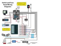
Gen wiring Diag 2.jpg

My problem appears to be a short circuit and I found this rather descriptive method of testing for a short circuit. " To find a short, look for continuity where it should 'not exist.' Disconnect the circuit from the battery and disconnect the equipment from the circuit. (to check a bilge pump fro example, disconnect the pump from the circuit.) There now should be no path from the hot side of the circuit to the ground side. Close all switches and circuit breakers and, using the most sensitive ohms scale (R X 1), test from any part on the hot side to any part on the ground side. (The terminals where the equipment was disconnected are generally the most accessible place.) The meter should show infinite ohms: Any other reading indicates a short; zero ohms a serious ("dead") short.

If there is a short, leave the ohmmeter connected across the terminals where the equipment was disconnected and switch off the nearest switch in the circuit (or pull a fuse). If the meter stays on zero ohms, the short is on the equipment side of the switch (or fuse). If the meter jumps to infinity, the short is on the other side. In the latter case, close the switch (or put back the fuse) and open the next switch back in the circuit. If the meter stays on zero ohms, the short is between the two switches; if it jumps to infinity, it is on the far side of the second switch. Continue this testing procedure.

If the original test (across the terminals the equipment connects to) showed no short, then the equipment itself may be shorted. Test across the equipment leads themselves (with the equipment still disconnected). You should expect to find some resistance - how much depends on the nature of the equipment. The higher its rated amperage, the lower the resistance."
Your going in the correct direction and should find all the circuits that have a problem
 
Top