Help please Mercury Control box and tach wiring 1987?

appleo

Petty Officer 1st Class
Joined
Jul 19, 2012
Messages
388
Have an older approx 1987 Mercury 70 . There is a cable exiting the control box. I believe supports tach. and maybe tilt trim indicator

Any help appreciated on mating instrument panel harness or color codes of wires appreciated

Thamks! Appleo
 

Attachments

  • photo326429.jpg
    photo326429.jpg
    2 MB · Views: 0
  • photo326430.jpg
    photo326430.jpg
    1.9 MB · Views: 0
  • photo326431.jpg
    photo326431.jpg
    661 KB · Views: 0
  • photo326431.jpg
    photo326431.jpg
    661 KB · Views: 0

Texasmark

Supreme Mariner
Joined
Dec 20, 2005
Messages
14,778
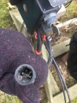
First off is it the cable that mates to the engine, or is that one attached to the engine as are the control cables? Assuming you don't have an electrical cable plugged into the engine and it's about the same length as your control cables then it mates to a plug in the engine.

Assuming that it's a pigtail, within 3' of the control box, it could be battery voltage and return, big pins, smaller 2 would be tach and switched power...switched by the ignition switch for dash instruments that you wanted to turn on and off coinciding with the ignition switch position.

If switched power is one of the large pins, then the other small pin could be for a tilt and trim power dash indicator.....wouldn't matter if you had TT or not, just the TT position signal would be wired so that those with and chose to have a dash indicator, using that control box, would have the signal source, powering through the two larger pins.

I don't know when color codes changed so telling you what is on what color probably wouldn't do any good.
 

appleo

Petty Officer 1st Class
Joined
Jul 19, 2012
Messages
388
Yes it's a unused pigtail extending 12" from the control box

The motor is already connected to the jumbo cable and running on the wooden stand with muffs
 

Texasmark

Supreme Mariner
Joined
Dec 20, 2005
Messages
14,778
Okayeeeee. Get out your voltmeter and check the pins:

One large pin probably has 12v with the switch off. Used to power cigarette lighter connectors where things like hand held spot lights are plugged in.
One small pin will acquire 12v when you turn the switch on and is power to your tach
One small pin will have a colored wire to it that will show up in your regulator/rectifer module in the engine...on 2000 up engines it's grey and goes to your tach signal terminal.
The other large terminal should be engine block casting referenced/battery ground....negative terminal.
 

appleo

Petty Officer 1st Class
Joined
Jul 19, 2012
Messages
388
Found the answer I believe . Resolved . Thanks
 

Attachments

  • photo326606.png
    photo326606.png
    638.3 KB · Views: 3

Texasmark

Supreme Mariner
Joined
Dec 20, 2005
Messages
14,778
Okayeeeee. Get out your voltmeter and check the pins:

One large pin probably has 12v with the switch off. Used to power cigarette lighter connectors where things like hand held spot lights are plugged in.
One small pin will acquire 12v when you turn the switch on and is power to your tach
One small pin will have a colored wire to it that will show up in your regulator/rectifer module in the engine...on 2000 up engines it's grey and goes to your tach signal terminal.
The other large terminal should be engine block casting referenced/battery ground....negative terminal.

PTT I think would be a wire to the main harness since the PTT switch requires power, up, and down......power from the main power input and (common wire) but needing separate up and down feeds to get the power back to the up-down relays in the engines with PTT.

On boats with a PTT switch up in the bow, like at the trolling motor position, I currently have and have had them but don't recall checking out the wire routing....but, thinking as I type, I think there is a separate 3 wire cable with plug supplied alongside the main electrical engine-to-control cable with current colors Red-power, blue-up, green -down relay drives.
 
Top