How to test ignition side of a stator

timmyg

Seaman
Joined
Jun 20, 2007
Messages
51
Does anyone know how I can test the ignition side of the stator on my 1976 Johnson 55 hp?

I changed my stator (with a used one) My old one overheated and melted down and I'm worried that may happen to the new (used) one.
I would like to be able to test it properly to find the problem.

Thanks, Timmy
 

Joe Reeves

Supreme Mariner
Joined
Feb 24, 2002
Messages
13,262
Re: How to test ignition side of a stator

Normally, the only reason the stator would melt down on that model engine would be if the charging system rectifier had failed for some reason. If you have a tachometer and it works properly, the charging system including the rectifer is okay. The rectifier can be tested as follows.

(Small Rectifier Description & Location)
(J. Reeves)

On most 2,3,4,6 cylinder engines, the small rectifier is located on the starboard (right) side of the engine just in front of the engines electrical wiring strip. There are a few older V4 engines that have the wiring strip on the rear portion of the engine and the rectifier would be located just under that terminal strip. The smaller horsepower engines usually have the rectifier located on the starboard side of the powerhead close to the carburetor area.

The rectifier appears to be a round object approximately one inch (1") in diameter and also about one inch (1") high. The base of it is sort of triangular in appearance and is attached to the engine with two (2) screws/bolts..... usually one screw/bolt is larger than the other. The rectifier, depending on which one your engine uses, will have either:

One Red wire, one Yellow wire, and one Yellow/Gray wire, or One Red wire, and two Yellow wires.

Note that either of the above rectifiers could have a fourth wire which would be Yellow/Blue

********************
(Small Rectifier Test)
(J. Reeves)

Remove the rectifier wires from the terminal block. Using a ohm meter, connect the black lead of the ohm meter to the rectifier base (ground), then one by one, connect the red lead of the ohm meter to the yellow, yellow/gray, then the red wire (some rectifiers may also have a fourth yellow/blue wire. If so connect to that also). Now, reverse the ohm meter leads and check those same wires again. You should get a reading in one direction, and none at all in the other direction.

Now, connect the black lead of the ohm meter to the red wire. One by one, connect the red lead of the ohm meter to the yellow, yellow/gray, and if present, the yellow/blue wire. Then reverse the leads, checking the wires again. Once more, you should get a reading in one direction and none in the other.

Note that the reading obtained from the red rectifier wire will be lower then what is obtained from the other wires.

Any deviation from the "Reading", "No Reading" as above indicates a faulty rectifier. Note that a rectifier will not tolerate reverse polarity. Simply touching the battery with the cables in the reverse order or hooking up a battery charger backwards will blow the diodes in the rectifier assy immediately.
 

timmyg

Seaman
Joined
Jun 20, 2007
Messages
51
Re: How to test ignition side of a stator

Thanks Joe,
I guess what I'm having trouble understanding is that if the charging side of the stator is not working properly, how is that overheating the coils for the ignition side of the stator?


Tashasdaddy, Thanks for that link, I'll read up on it.:)
 

Joe Reeves

Supreme Mariner
Joined
Feb 24, 2002
Messages
13,262
Re: How to test ignition side of a stator

When the rectifier is faulty, the charging properties of the stator cannot charge the battery. The result is that the voltage, current, magnetic field, whatever one wishes to call it, backs up at the stator resulting in excessive heat.
 

Vic.S

Rear Admiral
Joined
May 4, 2004
Messages
4,719
Re: How to test ignition side of a stator

The things that can cause problems to rectifiers and stators are:
  • Connecting the battery with the polarity reversed. That will blow the rectifier instantly. It may also damage the stator but I think the rectifier will go so quickly that it won't.
  • Disconnecting the battery while the engine is running. That can cause cause a surge in volts which is likely to damage the rectifier. That I think is what Joe is referring to.
  • A rectifier that has failed to a short circuit (on at least two of its diodes) will cause the battery to be connected to the stator. That will result in a high current flowing from the battery through the stator, overheating it and probably burning it out.

Running an engine without a battery being connected to the charging circuit will do no harm to the stator, or the rectifier unless its spec is extremely poor. It is disconnecting while running that causes the problems. Certainly no problem as far as the stator is concerned. If it was then engines with the stator just supplying AC for lighting would have to have the lights on all the time!

Just one final point if you use a digital meter for testing a rectifier use it on its "Diode test" setting if it has one. If not use the highest ohms range. No problem with old fashioned analogue meters but there is with many digital meters.
 

timmyg

Seaman
Joined
Jun 20, 2007
Messages
51
Re: How to test ignition side of a stator

Thanks guys, for all the info.


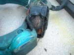
This is a pic of the old one. Would the extra heat from the charging side cause this?

I will check the rectifier tomorrow and post the results. I do know that the old one was not charging because there were several breaks in the windings.
But the new/used one seems to be charging fine with a volt test at the bat.

One thing that I've been thinking about is, If the charging side of the coils were getting hot enough to melt down the ignition coils then why aren't the charging coils melting also?

I'm getting a dark tar like drainage from the two large coils but the green charging coils show no signs of melting.
 

Attachments

  • DSCF0009-2.JPG
    DSCF0009-2.JPG
    48 KB · Views: 0

CharlieB

Vice Admiral
Joined
Apr 10, 2007
Messages
5,617
Re: How to test ignition side of a stator

Fine wire coils = high voltage, NOT part of the battery charging circuit.

Coils are wired in series, this coil had a short to ground, fed by the other coil(s) in its series, continued to burn/arc from the voltage produced by it's sisters, the engine may continue to fire until the arc length at the burn/short became greater than the voltage available.
 
Top