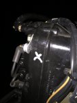
He already has that temp sensor, circled in post #4. Also with the way the Faria sensor is currently mounted it will be so inaccurate to be practically worthless.
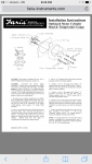
mtb55 - Sorry for your disappointment about not being bolt on, but it was a bolt on, wasn't it? Universal mounts usually require customizing.
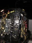
This is how you customize the install;
- Loosen the head bolt and rotate the sensor until the bracket is pointing to 3 o'clock.
- Snug the head bolt. Just snug, not torqued,
- Bend the bracket down against the side of the head.
- Remove the bracket and bend it slightly more than 90 degrees. Is is to hold the sensor tightly against the side of the head.
- Optionally smear some heat sink compound on the sensor for thermal heat transfer. This is not really needed.
- Bolt the bracket on with the head bolt, ensuring the added bend in step #3 positions the sensor tightly against the side of the head. Bend slightly more if needed.
- Torque the head bolt. All done.
You now have a belt and suspenders back up temp sender and gauge. The factory sensor is still the primary temperature monitor and will put the motor into limp or shutdown mode if or when the motor overheats.