Manual/Auto Aerator Switch

Blackhawk 65

Cadet
Joined
Aug 2, 2020
Messages
8
Re: Manual/Auto Aerator Switch

I think I now understand the system, below is how to rewire the switch to make it manual and automatic.

The reason for the rotary switch (2 in the drawing below) is to make the timer adjustable. Number 1 switch is non adjustable and works at one cycle speed, the #2 rotary switch can vary the cycle times.

If that is the case, and you would also like to make it work manually as well, all you have to do is rewire the switch as shown in the picture below.
Add a single green wire to one end terminal and splice it to the other green wire for manual. Put the red wire on the other end terminal of the switch, and the purple wire to the center terminal of the switch.

View attachment 149805

As far as that manual/auto switch goes, it's probably layed out for 6 or 8 terminals on the back, but only 4 used. The manufacturers only make one basic switch, the insides and number of terminals is changed for the type switch.

Here is one I found from Sierra as an example. The layout may change between manufacturers, you will need to determine how yours is layed out.

View attachment 149806
I know that this an old post. The wiring diagram you showed in your final post looks like what is on my boat. I have a 1991 Fisher SV-BY. I bought it used. The problem is that the previous owner did some poor wiring modifications to the aerator control. My question at this point is where does the violet wire connect to from the aerator switch to get the 12 volts. There is no fuse panel or fuse block on this boat, just individual in-line fuses. I will probably have other questions as I fix each problem I come across. Thank you for your time.
 

Blackhawk 65

Cadet
Joined
Aug 2, 2020
Messages
8
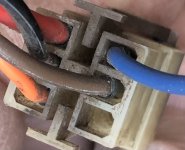
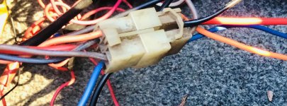
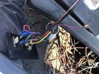
I have a 1991 FisherSV-18GT. I am trying to correct some very bad hack jobs on the electrical wiring. There is a black 10 ga and a red 10 gauge wire that was cut on a clear connector that came out from the main wiring harness, underneath the console. Where would these wires go- instrument switches, instrument gauges, or other. I am including picture attachments.


I also have a purple/red wire connected to the aerator control rocker switch. The other end is disconnected and have no idea where it goes. I did find this website for boat wire color code: https://www.electricaltechnology.org/2020/07/marine-boat-cable-wire-color-codes.html/amp


It shows: PURPLE: It is used for two purposes i.e. 1) wire an ignition switch to the coil and electrical instruments, 2) wire the distribution panel to electrical instruments in a marine.


I need your help where these these wires should be connected.


Thank you for you help
 

Attachments

  • 6B56837D-0CA4-43E9-ACA1-24EB6E89751E.jpeg
    6B56837D-0CA4-43E9-ACA1-24EB6E89751E.jpeg
    164.3 KB · Views: 1
  • 3439E99B-41C4-44B4-B2AA-AD9F84FCE6C1.jpeg
    3439E99B-41C4-44B4-B2AA-AD9F84FCE6C1.jpeg
    539.4 KB · Views: 1
  • 2F657366-E4AA-46C0-9366-0CFDC808D981.jpeg
    2F657366-E4AA-46C0-9366-0CFDC808D981.jpeg
    3.3 MB · Views: 1
Top