Merc 115 . 2 blown recitifiers on 2 motors?

ianmoore

Petty Officer 2nd Class
Joined
Jun 5, 2014
Messages
185
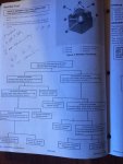
I installed a new tach about a week ago. After installation i launched the boat. Tach worked fine to about 4200RPM or so, and then would go down to zero. I did some research on possible causes, checked all connections(new) and everything checked out there. This morning i did the rectifier test from the Merc service manual. They have a flow chart of testing procedures. I followed it exactly:
You disconnect all connections from rectifier. connect positive lead of multi meter to ground and negative to "A" and "C", where the stator leads connect. I had no continuity. If you get that you reverse your meter leads and try the test again(black to grd and red to "a" and "c"). Again i had no continuity. According to the chart, this indicates a faulty rectifier.

I have almost exactly the same motor on my other boat. For grins i decided to test that rectifier. the tach in that boat works and I haven't noticed any funky charging issues. I performed the test and had the exact same results.

The meter is a good, working meter with a new battery. I'm positive that there is nothing wrong with the readings. I'm about to order 2 new rectifiers, for both engines, but thought it was worth a quick post to see if anyone with experience with these motors might see something else.

I did a stator test on both motors and they tested fine.

Ideas?
 

gm280

Supreme Mariner
Joined
Jun 26, 2011
Messages
14,605
ianmoore...STOP. Don't order any rectifier just yet. You stated yourself that the second engine had no problems and was charging the battery without issue. So if that is indeed a true statement, then there is no blown rectifier...period! Are you certain you have your meter set to OHMS and not voltage? What that test is doing is proving that the diodes are working properly. So when you test one direction they are blocking voltage from going through and that would be the high resistance or open reading. Then when you swap the red and black leads it should show a low resistance which mean it is allowing voltage to flow through. Look at it like a one way valve. Because that is exactly what it is but in electronic terms... So I suggest you verify your meter is good and set to the resistance scale (R X 100, or R X 1000 or more), and try it again... JMHO!
 

ianmoore

Petty Officer 2nd Class
Joined
Jun 5, 2014
Messages
185
Thanks for the post. I'm not definitive that the second engine was charging correctly, just that there wasn't an obvious problem with the charging system. I have taken the second boat out many times in the last 6 months with only one time having a weak battery. I took that anecdotal evidence in parallel with the tach working correctly as meaning that somehow the rectifier was able to send its charge to the tach and the charging system in general.

I tested the circuit with a serious meter that i use for building audio gear. I feel pretty confident on both understanding and reading the results. I am going to try it once again with another meter, but I am pretty sure that I am getting an open reading on both sides of the alternator to ground.
Will post in a couple of minutes
Thanks
Ian
 

ianmoore

Petty Officer 2nd Class
Joined
Jun 5, 2014
Messages
185
OK. A little more light, which is illuminating more confusion<g
I am using really good digital multimeters. Perhaps this is meant to be done with an analog meter?
I retested with both of my meters. One of them has an auto read of ohmage. I did that first, and then selected the range to 1k. Same results; open on both sides. The other meter had the same results. Both meters have a diode test function(this is the same as the continuity testing) On this setting, both meters registered .480 or so V with red to ground and black to a and then C. Reversed was open as it should be..
So, i moved on to the next step, which is connecting the meter black to the positive terminal of the rectifier and red to either "a" or "c". This is supposed to have continuity or the rectifier is considered bad. I tried continuity, as well as different ohm, scales on both meters..open, no continuity..both meteres. I tried the diode check for grins. The same result
 

gm280

Supreme Mariner
Joined
Jun 26, 2011
Messages
14,605
OK. A little more light, which is illuminating more confusion<g
I am using really good digital multimeters. Perhaps this is meant to be done with an analog meter?
I retested with both of my meters. One of them has an auto read of ohmage. I did that first, and then selected the range to 1k. Same results; open on both sides. The other meter had the same results. Both meters have a diode test function(this is the same as the continuity testing) On this setting, both meters registered .480 or so V with red to ground and black to a and then C. Reversed was open as it should be..
So, i moved on to the next step, which is connecting the meter black to the positive terminal of the rectifier and red to either "a" or "c". This is supposed to have continuity or the rectifier is considered bad. I tried continuity, as well as different ohm, scales on both meters..open, no continuity..both meteres. I tried the diode check for grins. The same result

ianmoore, if you are building audio gear that I would think you know how to use a meter. With that stated, the diode function appears to be showing a forward voltage of .480 volts. And when leads are reversed, it is open. That tells me your diodes are doing their job. So I would look for something else. Diode usually show between .3 or .4 to .6 or .7 voltage depending on the type... So maybe you have something else as the problem. Not being there and testing things myself, this is just from the info you provided. JMHO
 

ianmoore

Petty Officer 2nd Class
Joined
Jun 5, 2014
Messages
185
No Title

yes. I agree. the diode element of the rectifier seems to be working. I am a little foggy on the testing as I think the digital meter thing is changing the paramater of the test.
If you look at the flow chart for the test, you can see what I am following.I am wondering if there is a way to test between the positive terminal and the alternator terminal to see if they are working correctly
 

Attachments

  • photo226959.jpg
    photo226959.jpg
    162 KB · Views: 0
Top