Merc 850 Problem after Ignition R&R

SeaKaye12

Lieutenant Junior Grade
Joined
Jul 3, 2005
Messages
1,108
Hello!

S/N 4721196 1977 Merc 850 No Distributer.

Just finished replacing the Stator, Trigger and Internal Wiring Harness (All CDI Parts)

Engine fires and runs; but my electric choke button does not activate the choke solenoid.

Also, the engine will not shut off with the key.

BUT.....when the choke button is pressed; the engine kills.

Remember...the choke solenoid is not operating. It kills not because it is being choked; it kills as if the choke button was a kill switch.

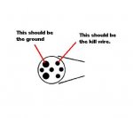
Choke is wired with the grey wire; the kill terminal on the switchbox is wired with the orange wire.

I have checked and re-checked wiring. All seems fine.

Any suggestions?

Thanks, Chuck
 

Wingedwheel

Lieutenant Junior Grade
Joined
Jun 16, 2009
Messages
1,071
Re: Merc 850 Problem after Ignition R&R

sounds like the switch is acting as a ground. Look for frayed or broken wires.
 

achris

More fish than mountain goat
Joined
May 19, 2004
Messages
27,468
Re: Merc 850 Problem after Ignition R&R

Sounds like you need to re-check the wiring. Point to point with a multimeter. If you have swapped the choke and kill wires in the harness somewhere that would account for the choke killing the engine. With the meter attached to the kill wire press the choke (key ON, engine not running). Does the wire read 12volts? If so, disconnect the wire on the choke solenoid and then check resistance to ground. If it reads open circuit (high resistance) turn the key OFF and re-check it. I suspect it will read as a short to ground.

Chris.........
 

SeaKaye12

Lieutenant Junior Grade
Joined
Jul 3, 2005
Messages
1,108
Re: Merc 850 Problem after Ignition R&R

Thanks for the replies....

achris; I did the tests that you suggested and here are the results:

>>>With the meter attached to the kill wire press the choke (key ON, engine not >>>running). Does the wire read 12volts?

No.

>>If so, disconnect the wire on the choke solenoid and then check resistance >>to ground. If it reads open circuit (high resistance) turn the key OFF and >>re-check it. I suspect it will read as a short to ground.

No short to ground with key in either position.

Isn't this nuts???? It's a simple single grey wire that goes to the choke. And it's a simple orange wire that goes to the kill terminal on the box. How can something that simple be causing these issues?

I've already check the terminals on the new harness...they are all identical to those on the old one; and the wiring to the controls has been in place and un-molested since 1977. Everything was working perfectly until a disintegrated trigger wire caused me to do this repair.

Any other suggestions achris? Anyone else?

Chuck
 

achris

More fish than mountain goat
Joined
May 19, 2004
Messages
27,468
Re: Merc 850 Problem after Ignition R&R

Arrrr...

Not nice!!!

ok... With the wire disconnected from the choke solenoid, does pressing the button kill the engine? Also with the wire disconnected does the solenoid work when you touch it with a live 12 volt wire?

Kill circuit. Remove the kill wire from the switchbox (orange). With the key ON is there continuity to ground? Turn the key to OFF, continuity?

FYI... The way these engines are stopped is to discharge the capacitor by grounding the 'kill' wire. When the key is ON the wire should be open circuit. Key OFF, wire grounded. As far as 400 volts is concerned (capacitor voltage), if the wire is tied to 12v, that's as good as ground and will still kill the engine.

Do you have a wiring diagram for your engine?

Chris........
 

SeaKaye12

Lieutenant Junior Grade
Joined
Jul 3, 2005
Messages
1,108
Re: Merc 850 Problem after Ignition R&R

Thanks so much achris for the last reply. Here's the results:

>>ok... With the wire disconnected from the choke solenoid, does pressing the button kill the engine?
No.

>>Also with the wire disconnected does the solenoid work when you touch it with a live 12 volt wire?
Yes

>>Kill circuit. Remove the kill wire from the switchbox (orange). With the key ON is there continuity to ground? Turn the key to OFF, continuity?
No on both counts

Now; some other observations:
(1) My tach is not working
(2) With the tach unplugged at the control, pressing the choke button does NOT kill the engine. (It doesn't operate the solenoid either...)
(3) The stator is not charging. The voltage (at a dash gauge) stavs right at 12v regardless of RPM...
(4) I did a test of the rectifier according to the manual and it tested bad. I can give you details if that would help.

So; in addition to everything else; my other question is: Did I cause the failure of the rectifier? If I wire up another one will it blow immediately?

Sheesh....

Thanks again for sticking with me on this achris....

Chuck

PS Yes I do have the correct wiring diagram. I have the genuine Merc manual for the engine.
 
Last edited:

achris

More fish than mountain goat
Joined
May 19, 2004
Messages
27,468
Re: Merc 850 Problem after Ignition R&R

Chuck,

This one sounds like it could be fun :p.... I have little doubt that if I was there in person we would find it quite quickly, but I have to work though your eyes and hands... :D so it will take a little longer....

So far so good. I like that you do exactly as I ask and reply in the right way... We will work well together. You have the diagram and sound like you know which end of a meter to hold, excellent.....

For the moment we will ignore the failed rectifier, just disconnect the wires to it and tape them off. Once we have everything else sorted out we'll come back to it. There is a chance that a wiring fault killed the rectifier, that's why we won't go after that first. ;) It may explain the tacho not working and the voltage not moving, but later.... Just one question on the tacho. When the key is OFF the tacho needle usually points up around the 1000 mark. Yes? When you turn the key ON does the tacho drop back to 0? (This will verify that we have 12v to the tacho).

Disconnect the big plug on the side of the engine and check that each pin goes to the correct wire (in the engine) and that wire is connected to the right place. You mentioned that you have a new (CDI) harness. Does it have the same colours as the original or are you having to fight though a colour change too?

While you are checking that wires are going to the right place, also check that they are not going to the wrong place (looking for a short in the harness). We disconnected the engine harness plug to isolate it from the control box and instrument harness. I use a 'divide and conquer' troubleshooting technique.

Once we have verified that all the wires are good in the engine we can turn our attention to the control and instrument system (if necessary).

Since all you changed (I assume) is inside the engine and everything was working before the change, then the problem is most likely inside the engine (but not definitely, we could still have a coincidental failure in the external harness, so we will not rule that out just yet).

Good luck and hear from you soon.

Chris...........
EDIT: Chuck, I have just had a look on the CDI website and noticed that there are 2 Merc harnesses that look very similar for your engine. One is the right one and the other is for the same engine, but with a distributor (what's called a 'battery ignition'). Please verify that you have the correct harness for your (distributor-less) engine. The CDI part number should be 414-3369.
 

SeaKaye12

Lieutenant Junior Grade
Joined
Jul 3, 2005
Messages
1,108
Re: Merc 850 Problem after Ignition R&R

Hi Chris et al....

>>Just one question on the tacho. When the key is OFF the tacho needle usually points up around the 1000 mark. Yes?

The tach would stay pointed at whatever RPM the engine was at when it was shut down. Then when the key was turned to "ON" the pointer would drop to zero.

>>When you turn the key ON does the tacho drop back to 0? (This will verify that we have 12v to the tacho).
Yes

>>Disconnect the big plug on the side of the engine and check that each pin goes to the correct wire (in the engine) and that wire is connected to the right place.

When I first received the CDI harness; I tested continuity on each terminal and it's respective wire ends. All was OK. I re-tested that again today. I disconnected each wire one by one and re-certified that it was making continuity with only the appropriate terminal in the plug. All seems OK. I also have checked, re-checked and checked again that they are going to the right place on the engine. CDI's instructions seem to match what was there before, and also seem to match the wiring diagram.

>>You mentioned that you have a new (CDI) harness. Does it have the same colours as the original or are you having to fight though a colour change too?

Same colors (colours.... :)

>>While you are checking that wires are going to the right place, also check that they are not going to the wrong place (looking for a short in the harness).

I have checked that the best I can with the VOM and I see no problems

>>Since all you changed (I assume) is inside the engine and everything was working before the change,
Yes; correct.

One question: The CDI harness came with two jumper wires that I have not used. Their instructions say that they are to be used as jumpers for "RECTIFIER TO STATOR" "IF NEEDED". I don't know how they would be needed; the Stator already connects to the rectifier with the two yellow/red wires. In looking over the wiring diagram I don't see that they would be needed. Am I missing something?

Another thing that I'll mention: The boat's wiring harness (the one from the engine plug to the control) has an extra connection on it that neither the original internal harness or the new CDI internal harness have. It shows that way on the wiring diagram as well. It's the plug that has the white wire connected to it. Don't know if that tells you anything...but it's no different than its always been....

Thanks so much Chris....I'll wait to see what you suggest next....

Chuck
 

achris

More fish than mountain goat
Joined
May 19, 2004
Messages
27,468
Re: Merc 850 Problem after Ignition R&R

Oh boy!!!

Ok, first things first. The white wire in the harness is a hangover from the old distributor engines. The battery ignition systems needed a 12 volt supply to tell the ignition box to fire up. The 2 jumper sin the kit for the rectifier/stator are if the rectifier needs to be relocated.

I'm now at a loss.

Ok, here's what I would do next.

Leave all the wires from the engine plug disconnected. Disconnect the POSITIVE cable from the battery. Connect black wires in the harness to their respective point on the engine.
Plug the harness back into the engine.
Run a long wire from the negative terminal on the back of the tacho (or voltmeter) to the engine. Now check you have continuity from the negative of the tacho to the battery negative post. If not, find out why. If it's good, next step.

Check continuity between the engine block and the orange wire (kill). With the key OFF it should be hard to ground, with the key ON it should be open circuit. I suspect this will be faulty, so I'll outline checking this now. If it's good just move to the next step. Disconnect the harness plug and check continuity between the 2 pins in this drawing. Should be open with the key ON and short with the key OFF. Verify the large hole is ground by checking it against the ground wire on the back of the tacho (or voltmeter).

attachment.php
/​

If that's not the case, with one lead of the meter in the large hole (ground) look for another hole that does show short with the key OFF and open with it ON. This may be where we have (one of) the problems. If all is good, next step.

Connect the red terminals in the engine harness to their places in the engine (but not to the rectifier). Connect the red lead to the battery POSITIVE. Check you have 12 volts between the engine block and the large red terminal on the starter solenoid. If that's good, turn the key to ON. Tacho should drop to 0 and the voltmeter should read. If not, fix it. If that's good, next step.

Check that the Brown wire in the harness is continuous to the signal wire on the back of the tacho. The Brown wire should be connected to either of the yellow wires on the rectifier. Verify that the rectifier is/was connected correctly, and its base grounded properly. As for replacing the rectifier I would just go to any electronics shop and buy a bridge rectifier, with a rating of not less than 20 amp and 100 volts, and put that in. They cost about $4, a whole heap cheaper than a genuine item (this is one of the few times I recommend non genuine).

If all that is good, then I can't see what's wrong....

Chris...........
 

Attachments

  • Merc connector.jpg
    Merc connector.jpg
    9.2 KB · Views: 0
Last edited:

SeaKaye12

Lieutenant Junior Grade
Joined
Jul 3, 2005
Messages
1,108
Re: Merc 850 Problem after Ignition R&R

Lets be sure that we're both looking at the boat harness plug the same way. There's mine in the picture....

Terminal 1:Yellow (Starter Solenoid)
Terminal 2: Grey (Choke)
Terminal 3: Orange (Kill)
Terminal 4: Red
Terminal 5: Black
Terminal 6: Brown (Tach)

I'm about to start the other tests; I'll post back when I'm done

Chuck
 

Attachments

  • boatharnessplug.jpg
    boatharnessplug.jpg
    141.7 KB · Views: 0

SeaKaye12

Lieutenant Junior Grade
Joined
Jul 3, 2005
Messages
1,108
Re: Merc 850 Problem after Ignition R&R

OK Chris...we might be on to something :)

>>Leave all the wires from the engine plug disconnected. Disconnect the POSITIVE cable from the battery. Connect black wires in the harness to their respective point on the engine.
Plug the harness back into the engine.
Run a long wire from the negative terminal on the back of the tacho (or voltmeter) to the engine. Now check you have continuity from the negative of the tacho to the battery negative post.

OK so far....

>>Check continuity between the engine block and the orange wire (kill). With the key OFF it should be hard to ground, with the key ON it should be open circuit.

No continuity with key either on or off.

>> Disconnect the harness plug and check continuity between the 2 pins in this drawing. Should be open with the key ON and short with the key OFF.

Key Off = 20-25 ohms
Key on= OPEN

>>Verify the large hole is ground by checking it against the ground wire on the back of the tacho (or voltmeter).

Yes. Verified

>>If that's not the case, with one lead of the meter in the large hole (ground) look for another hole that does show short with the key OFF and open with it ON.

I don't see any problems there.

HERE IS WHERE I WAS SURPRISED:

>>Connect the red terminals in the engine harness to their places in the engine (but not to the rectifier). Connect the red lead to the battery POSITIVE. Check you have 12 volts between the engine block and the large red terminal on the starter solenoid.

Well; there are only two red wires; the heavy one to the solenoid and the light one to the rectifier (which has been dis-connected already) THE VOLTMETER SHOWS ONLY 3.5-4 VOLTS AT THE SOLENOID. The reading at the battery itself is appx 13v. as is the reading at the dash gauge.

>>Check that the Brown wire in the harness is continuous to the signal wire on the back of the tacho. The Brown wire should be connected to either of the yellow wires on the rectifier. Verify that the rectifier is/was connected correctly, and its base grounded properly.

Yes, Yes, Yes.

So; what do you make of that? BTW....when I hooked everything back up; voltage at the starter solenoid was 13v; same as the battery.

Chuck
 

achris

More fish than mountain goat
Joined
May 19, 2004
Messages
27,468
Re: Merc 850 Problem after Ignition R&R

Love your picture with the terminal numbering... I don't have one of those plugs here so I couldn't take a picture like that.... Those terminals look nice and clean too. One thing I have just remembered is that sometimes the pins in the engine harness need just the tiniest of spreading to make sure they make good contact when you push the plug in (if they are the same as the original Merc ones. They were split pins).

So, measuring voltage from the large red lead on the solenoid to the engine block revealed only 3.5-4 volts... THAT was unexpected.

And this is scary...

when I hooked everything back up; voltage at the starter solenoid was 13v; same as the battery.

Appears there is a voltage loss somewhere. Question is, is it in the negative lead or the positive. That's really easy to find out. :)

With ONLY the black and red wires connected.

We need to do a voltage drop test on each of the leads.

We'll start will the negative. Put the black lead of the multimeter on the battery negative POST, not the terminal, the lead post the terminal attaches to. Put the red lead of the meter to a clean spot on the engine block. We should see 0 volts. If you do, we check the positive lead the same way. If you have more than 0 volts, start working the red meter lead back towards the battery post, looking for the point where the voltage drops to zero. So the next test point after the engine block would be the terminal on the end of the battery lead, where it bolts to the block, then the terminal on the end of the lead at the battery end, then the terminal itself.

To test the positive side put the RED meter lead on the battery positive POST and the black meter lead on the terminal on the solenoid that the red battery lead bolts to. If the meter reading is not 0, then again work your way back towards the battery.

Also check that there is no voltage between the engine block and any of the black wires in the harness (looking for bad grounds).

Good luck again.... We'll see what this reveals... :D

Chris.............
EDIT: Just reread your post and this jumped out at me...

>>Check continuity between the engine block and the orange wire (kill). With the key OFF it should be hard to ground, with the key ON it should be open circuit.

No continuity with key either on or off.

>> Disconnect the harness plug and check continuity between the 2 pins in this drawing. Should be open with the key ON and short with the key OFF.

Key Off = 20-25 ohms
Key on= OPEN

What's wrong with this picture? It appears that the plug end of the kill wire is good, but the engine end of it isn't. Either there is a ground wire problem or the kill wire problem in the engine harness. Do you follow that?

One more test. Only the black wires and the red wires connected (in the engine) and the plug disconnected, check continuity from the large ground pin (#4 in your pic, but the connector on the engine not the end of the control box harness) to the engine block. What do you get?
 

SeaKaye12

Lieutenant Junior Grade
Joined
Jul 3, 2005
Messages
1,108
Re: Merc 850 Problem after Ignition R&R

I'm spending time today just generally cleaning up all the ground connections I can find. I'll do your testing after I'm done with that.

One question: I put the ohm-meter lead on the heavy black cable attached to the starter at the top. I put the other lead on other engine ground points.....and I get no continuity.

How is that even possible?

Am I going nuts here?

Chuck
 

SeaKaye12

Lieutenant Junior Grade
Joined
Jul 3, 2005
Messages
1,108
Re: Merc 850 Problem after Ignition R&R

achris et al....the results of the latest tests:

>>We need to do a voltage drop test on each of the leads.

>>We'll start will the negative. Put the black lead of the multimeter on the battery negative POST, not the terminal, the lead post the terminal attaches to. Put the red lead of the meter to a clean spot on the engine block. We should see 0 volts.

I get -0.02 (minus 0.02) I don't know if that's close enough to zero or not.


>>To test the positive side put the RED meter lead on the battery positive POST and the black meter lead on the terminal on the solenoid that the red battery lead bolts to.

I get 0.02 (not minus) Again; not sure how to interpret that.

>>Also check that there is no voltage between the engine block and any of the black wires in the harness (looking for bad grounds).

Again I get 0.02

>> It appears that the plug end of the kill wire is good, but the engine end of it isn't. Either there is a ground wire problem or the kill wire problem in the engine harness. Do you follow that?

I think so.... :)

>>One more test. Only the black wires and the red wires connected (in the engine) and the plug disconnected, check continuity from the large ground pin (#4 in your pic, but the connector on the engine not the end of the control box harness) to the engine block. What do you get?

I get no continuity. How is that possible?

As frustrating as this is getting to be...I kinda enjoy it all. I will certainly know a lot more about my engine after I get this solved. Chris; thanks so much one more time. If this all tells you something; please share it with me.

Chuck

PS....also if you haven't already...please also read the previous post from me in this thread about the starter cable continuity....
 

achris

More fish than mountain goat
Joined
May 19, 2004
Messages
27,468
Re: Merc 850 Problem after Ignition R&R

>>One more test. Only the black wires and the red wires connected (in the engine) and the plug disconnected, check continuity from the large ground pin (#4 in your pic, but the connector on the engine not the end of the control box harness) to the engine block. What do you get?

I get no continuity. How is that possible?....

I'm spending time today just generally cleaning up all the ground connections I can find. I'll do your testing after I'm done with that.

One question: I put the ohm-meter lead on the heavy black cable attached to the starter at the top. I put the other lead on other engine ground points.....and I get no continuity.

How is that even possible?

Am I going nuts here?

Chuck

Chuck,

How is that possible? Because the starter motor has rubber insulating mounts. I believe we are onto the problem.

Ok, it's been a few years since I worked on an engine like yours, so correct me if I'm wrong. The negative battery lead connects to the starter motor... There should also be another short black lead from the starter motor to the engine block. You need to run around all those leads and bolts to see where you've losing the ground connection.

Chris.........
 

SeaKaye12

Lieutenant Junior Grade
Joined
Jul 3, 2005
Messages
1,108
Re: Merc 850 Problem after Ignition R&R

Chris; you are correct in that the starter is mounted in rubber. I discovered that when I started de-mounting it today.

As for another black wire; I don't see one. Only the Heavy Yellow wire that goes to the solenoid.

The attached image file shows no second black wire either.

I think I need to add a wire connecting harness ground to the engine block.

I look back at the CDI instructions and I think they made an error. Their instructions say run a black jumper wire from the SwitchBox to Engine ground. I did not do that because there is already one there. (See Pic)

I believe that their instructions should have said "Run a black jumper wire from the thin black wire connecting to the starter solenoid to engine ground." Or, "Run a black jumper wire from the heavy black wire connecting to the negative starter terminal to engine ground".

I would appreciate seeing what you have to say about my diagnosis.

Chuck
 

Attachments

  • 10.jpg
    10.jpg
    8.3 KB · Views: 0
  • groundwire.jpg
    groundwire.jpg
    145.9 KB · Views: 0

achris

More fish than mountain goat
Joined
May 19, 2004
Messages
27,468
Re: Merc 850 Problem after Ignition R&R

That is correct, you need to have very good connections between the starter motor, the engine block, the switchbox and the battery negative...

Connect a good ground wire from the starter motor (use the same mounting point as the battery lead) to the engine block.

We close :D:D:D
 

achris

More fish than mountain goat
Joined
May 19, 2004
Messages
27,468
Re: Merc 850 Problem after Ignition R&R

The normal run method it to bolt the battery lead to the engine block with one of the bolts on the lower starter motor mounting, and a short thick black lead from one of the top mounting bolts to the starter motor itself....
 

achris

More fish than mountain goat
Joined
May 19, 2004
Messages
27,468
Re: Merc 850 Problem after Ignition R&R

OK Chris; I'll pick and choose among the methods to get that accomplished.

I still have a hard time understanding how the engine could run that way.

It ran because the starter motor had good connections, so you could start it. The ignition system ran because it's independent of the battery altogether. Once the flywheel is spinning the current produced in the stator goes to the switchbox, not the battery. You had good contact between the stator ground and the switchbox.

The places where there would have been a problem :

1. The choke, needs the ground from the battery as the 12 volts it uses is reference to the battery, and the engine block wasn't connected to the battery ground.
2. The tacho also needs engine ground because the pulse is from the alternator which grounds through the engine block.
3. Kill circuit, because at the key it grounds the kill wire to the battery ground, not the engine block ground if they aren't connected together, as was your case.....

SeaKaye12 said:
I just picked up one of these locally...

http://www.mouser.com/ProductDetail/NTE/NTE5340/?qs=qnIibUs0EsB8f8uqD7KZzA==

Should be OK; eh? 200V; 40A

Perfect. You ok to connect that up are you want some help?

SeaKaye12 said:
Do you think that I've damaged anything else in all this?

Chuck

I think everything else should be ok....

Well done.....

Chris.............
 
Top