Mercruiser 120 Coil Overheating Like Many Other Members

Status
Not open for further replies.

lognum

Seaman
Joined
Aug 30, 2012
Messages
69
Cheers Forum Mentors. Looking for some guidance and hopefully a resolution. I see a lot of the same issues with coils posted here, but never a viable solution. Hoping this time around, there may be one. I have a merc 120 serial number A635702. It was changed from the traditional points, to an electronic ignition (Sierra Model 18-5297) with a Flamethrower coil with 3ohm internal resistance (prior was a coil needing external resistance). No matter what the set up, the coil still overheats after about 40-50 minutes and engine cuts out. Wait 5-10 minutes, and good to go again. This latest set up has 12volts going directly into the ignition module (red wire on the distributor), purple yellow and purple resistance wire on the + side of the coil and grey tach and black wire, from the distributor, on the - side. Motor starts great and runs smooth till the allotted time, then rpms go out of whack and it dies. Not a good feeling on the water. This wire set up was suggested by experienced mentors in this forum, but need a little more advice. The alternator is not original and the new one is self regulating. The wires that were connected to the original alternator, were removed (red, purple, and a black one) and now sit taped separate connected to nothing (can this be the issue?). Voltage at the positive side of the coil and negative is all within the advised specs mentioned in this forum, including alternator. Can a faulty ignition module be the issue? What can cause the coil to overheat, even with an external resistance (purple choke wire) and internal resistance (flamethrower 3ohm coil)?? Had both an internal and external resisted coil, still the same darn issue. Your kind assistance is requested.
 

achris

More fish than mountain goat
Joined
May 19, 2004
Messages
27,468
Sounds like you've ruled out all the things I would suggest checking, including the alternator output voltage... All that's left is the module....

Have you contacted Petronix?

Chris....
 

lognum

Seaman
Joined
Aug 30, 2012
Messages
69
Thanks Chris. Yes, contacted Petronix in California. They said that the coils can get up to 200degrees, but the coil still seems to overheat and cause the issue. Wait 5 minutes and the engine starts again. Can't be normal. At my wits end:(
 

lognum

Seaman
Joined
Aug 30, 2012
Messages
69
After reading many forum posts, with the same similar issue, there has to be a common thread that connects all of us. No one has ever said, "coil has stopped overheating". Whomever figures that out, would help many of us:)
 

Scott Danforth

Grumpy Vintage Moderator still playing with boats
Staff member
Joined
Jul 23, 2011
Messages
50,234
check for spark. if you still have spark, suspect fuel issues.
 

zellerj

Petty Officer 2nd Class
Joined
Dec 13, 2017
Messages
136
The coil overheat problem has been discussed extensively on the Moyer Marine Atomic 4 forum. The conclusion is that you need 4 to 4.5 ohms of total resistance on the coil with an electronic ignition. Although Mercruisers are different than the old atomic 4, the principles are the same. Some Atomic 4 owners also moved the coil to the bulk head to keep it cool. Buy a few ballast resisters and put them in the + circuit, measure the voltage coming to the coil and measure the temperature of the coil after running a while, and report back. Most coils need about 4 amps so you need to add a ballast resister to get the amps low enough to keep them from overheating. Coils will generally fire at 8 volts, so adding more resistance will probably not affect the starting. My bet is that the coil will work well. Also your current coil may be toast already, so I would use a new one. .
 

Bt Doctur

Supreme Mariner
Joined
Aug 29, 2004
Messages
19,344
I think the problem lies in the fact the coil is always under power from the electronic conversion unlike a points system that cuts the power when the points open. 12 volts with 3 ohms is 4 amps constant doubling the resistance reduces the amps by 1/2 so now you pulling 2.4 amps
 

nola mike

Vice Admiral
Joined
Apr 22, 2009
Messages
5,410
I think the problem lies in the fact the coil is always under power from the electronic conversion unlike a points system that cuts the power when the points open. 12 volts with 3 ohms is 4 amps constant doubling the resistance reduces the amps by 1/2 so now you pulling 2.4 amps

is that the case? My understanding is that the module is switching power to the coil just as the points did off the negative side.
 

Bt Doctur

Supreme Mariner
Joined
Aug 29, 2004
Messages
19,344
the module is magnetic unlike a set of points that physically open. Spark occurs when the magnetic field in the coil windings collapse`s , after charging the coil the poins open and that collapses the field causing the spark to be generated.
 

nola mike

Vice Admiral
Joined
Apr 22, 2009
Messages
5,410
The coil is still seeing the same thing though, a switching of the ground terminal, and still generates a spark in the same manner regardless of whether there switch is mechanical or electronic. In neither case is the coil seeing constant current.
 

achris

More fish than mountain goat
Joined
May 19, 2004
Messages
27,468
The coil is still seeing the same thing though, a switching of the ground terminal, and still generates a spark in the same manner regardless of whether there switch is mechanical or electronic. In neither case is the coil seeing constant current.

Quite correct. ;)
 

lognum

Seaman
Joined
Aug 30, 2012
Messages
69
Thanks for the input all. Will try the added ballast resistors and see. Just a foot note, the coil I am using hasxa 3ohm internal resistance and Icalso have the purple resustance wire on the + side. Will let you know. Cheers.
 

achris

More fish than mountain goat
Joined
May 19, 2004
Messages
27,468
Ah. The modules sense current. If you have a 3 ohm coil and the resistance wire still in circuit, the current will not get high enough. The module may be trying to let current flow longer than normal in order to try to get the current up (that is, increasing the dwell). That will cause overheating. Try running a normal wire as the power feed.

And adding ballast resistors will make it worse, not better.
 

lognum

Seaman
Joined
Aug 30, 2012
Messages
69
Achris, I used a coil that needed external resistance, prior to the current Flamethrower 3ohm coil, and it did the same thing (heated up and the engine stopped after 50 minutes). I tried taking the purple resistance wire off the + side and ran a constant feed (ignition switched) wire, and it did the same thing, but also did not restart as well. I tried every combination of switched and resistance wire on the coil and module.... and the same thing happened (coil over heated). There has to be something else going on. As in the electronic schematic of a Merc 120/140, that so many have posted, the purple wire runs to the choke and to the original alternator. Now that there is a self regulating alternator, and the purple resistance wire is in the harness, terminates to the choke, but nothing else (as it is just taped off beside the alternator), could this be a cause?

Cheers,
 

achris

More fish than mountain goat
Joined
May 19, 2004
Messages
27,468
The purple wire running to the choke is not a resistance wire, it's 'full feed'...
 

lognum

Seaman
Joined
Aug 30, 2012
Messages
69
Understood, but in the wiring schematic it shows a dotted resistance wire, going to choke (purple) and then splitting off to the alternator. Is this not how it is understood?
 

lognum

Seaman
Joined
Aug 30, 2012
Messages
69
If it's a full 12v feed, how does the resistance come into play? See attached image.
 

Attachments

  • Merc 120.jpg
    Merc 120.jpg
    77 KB · Views: 5

achris

More fish than mountain goat
Joined
May 19, 2004
Messages
27,468
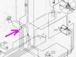
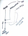
Full 12v is fed to the choke heater. A resistance wire is t-ed off the feed to the choke (at the pink arrow) and run to the coil. No resistance to the choke, resistance wire to the coil....

Click image for larger version  Name:	resistance.JPG Views:	1 Size:	34.7 KB ID:	10635285

Here's another way of looking at it....

choke.JPG

Chris.........
 
Last edited:

lognum

Seaman
Joined
Aug 30, 2012
Messages
69
Okay, thanks Chris. Now we are getting somewhere. That purple "resistance wire" is not dropping to 7V for some reason. Could it be because it is no longer connected to the alternator? Would it not make sense then to put a ballast resistor in that line, before the coil, to drop it from 12V to 7V, or, do you suggest something else? Also, if 12V is going to the choke and 12V is going to the alternator, from the purple wire, what is the methodology that drops it to only 7V on that same purple wire to the coil? Cheers.
 

achris

More fish than mountain goat
Joined
May 19, 2004
Messages
27,468
It drops the voltage at the coil positive by a principle known as voltage dividing. When you have 2 resistances in series, between a positive voltage and ground, the voltage at the junction of those 2 resistors will be a proportion of their resistances.

For example, if you have 2 equal resistances between 12 volts and ground, the centre point will be 6 volts. With our coil example, if the coil is 1.5 ohms and the resistance wire is 1 ohm, the point where they join, the coil +, will be 7.2v. (1.5/2.5*12v).

We also have Ohm's law to consider. With a total resistance of 2.5 ohms, a maximum current of 4.8 amps can flow. But as a coil is an inductor, the current will take time to reach maximum.

The module senses the current flowing, and a coil is usually fully charged at about 4amps. The module will try to set up the 'on' time until it sees 4 amps flowing before it fires the spark. If you add resistors, then the maximum current will never reach 4 amps.. (anything over 3 ohms resistance in a 12 volt circuit will have less than 4 amps flowing)...This is why adding ballast resistors will make it worse.

Hope this helps...

Chris......
 
Status
Not open for further replies.
Top