ratdude747
Petty Officer 1st Class
- Joined
- Sep 30, 2023
- Messages
- 296
Been rebuilding the alternator out of my 1976 Mercruiser 888 (302) and wanted to note some findings and info that don't seem to be on the forum already. Also, I noticed that another member with the same engine may be having an alternator issue, so I figured I better get the info out there.
This alternator, despite being mounted to a Ford engine, is actually a modified Delco-Remy (GM) 10si. The modifications are:
Here is what the stock electronics looked like:

What makes this weird is that somebody (mercruiser?) appears to have modified a stock voltage regulator by adding a stud to the feedback terminal, which in turn is jumpered to the field terminal (what's under the tape). The regulator is literally a stock GM part with said stud drilled and epoxied on. Additionally, most 1-wire rebuild kits either just use a modded voltage regulator (omit no parts, other than the resistor that the mercruiser setup already omitted), or use a modded voltage regulator with the extra stud, two jumper wires, and no diode pack... this is a weird hybrid approach that nothing currently sold seems to follow.
I made the mistake of ordering a stock rebuild kit (I'm mainly a Ford guy, who knows 1G/2G/3G but didn't know much on Delco-Remi SI alternators). And while technically I could try to de-epoxy the stud from the old regulator and drill/epoxy the new regulator, I didn't think this was feasable or a good idea. And unlike 1976, out-of-the-box one-wire conversion parts are readily available.
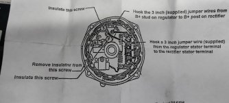
After doing a lot of reading around the web, I finally settled on the Transpo D10AC regualtor kit. This a 2-jumper style kit. Reportedly, unlike other 1-wire kits, they don't have nearly as high of a minimum RPM to initiate charging (which in hindsight is the issue I was having- no charge at 900RPM idle yet I recall it working at higher RPM in the past). Here is what the instructions say to do:

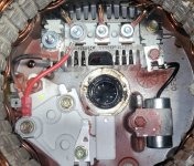
And here is what I actually did:

The nut for the new regulator was missing, thankfully the old one was the right thread. I also reused the one jumper wire due to the provided wire being too long to fit will (and I was too lazy to crimp a new jumper).
Otherwise, the rebuild is the same as a standard 10si rebuild. Plenty of guides on the web for this already, so I won't go there.
Other tips/info:
Make sure the screens get cleaned- mine were packed and not flowing air!

I did have issues with the rear torrington (needle cap) bearing... it was so tight that it broke on removal, and I had to use a torch (carefully) and a lot of beating to get the rest out. Installation was just as bad; I had to use heat on the shell, freezer on the bearing, and even then, it refused to press completely flush (1/8" stickout). This still worked... it slightly interfered with the rear screen, but the sheet metal is flexible enough that I was able to make it work. I did pack in some fresh grease since the stock grease wasn't much and was pretty cooked from the heat. I used some high-temp wheel bearing grease as that's what I had on my bench handy to use (it's well enough buried that I didn't see a need to use marine grease here).
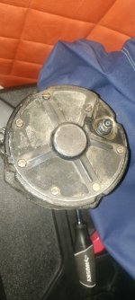
On reassembly, one has to change the order of operations. After installing the rear shell, one must pull the keeper pin from the brushes first before adding bolts and the end cover, as the added cover blocks the pin removal hole in the shell. Also, don't forget the extra output stud insulator... it's not a part in the kit (obviously), but any fiber/rubber washer that size will work if the existing one is shot).
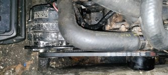
Installed with a fresh belt (old belt was an older non-toothed one- still passable and a good spare):

Once I get a couple other issues resolved (mainly, getting muffs that'll work right per my other thread), I'll report on how charging performance is. Replacement alternators for these things are pretty pricey ($250ish, although I found somebody supposedly selling them for $120 on sale???)... Had I bought a full 1-wire conversion kit (which included all of the non-1-wire rebuild parts), I'd maybe have $35 invested here. As far as being USCG/SAE compliant, all of the "special" parts needed for such (screens and the one insulator) are still there... everything new was either jumper wires or a replacement for an already-automotive part already inside the alternator case/screens... no change.
This alternator, despite being mounted to a Ford engine, is actually a modified Delco-Remy (GM) 10si. The modifications are:
- Added spark/flame arrestor screens to the front half of the case, inside the case (held by front bearing retainer)
- Added additional cap to back of alternator (held by main alternator bolts) with an extra positive stud insulator, more spark arrestor screens, a grounding tab, and coverage for the disused 2-wire connector (see below)
- Conversion from a 3-wire alternator to a 1-wire alternator. There are several designs for this, and the design they used is a bit peculiar (and not avialable to buy, see below for fix)
Here is what the stock electronics looked like:

What makes this weird is that somebody (mercruiser?) appears to have modified a stock voltage regulator by adding a stud to the feedback terminal, which in turn is jumpered to the field terminal (what's under the tape). The regulator is literally a stock GM part with said stud drilled and epoxied on. Additionally, most 1-wire rebuild kits either just use a modded voltage regulator (omit no parts, other than the resistor that the mercruiser setup already omitted), or use a modded voltage regulator with the extra stud, two jumper wires, and no diode pack... this is a weird hybrid approach that nothing currently sold seems to follow.
I made the mistake of ordering a stock rebuild kit (I'm mainly a Ford guy, who knows 1G/2G/3G but didn't know much on Delco-Remi SI alternators). And while technically I could try to de-epoxy the stud from the old regulator and drill/epoxy the new regulator, I didn't think this was feasable or a good idea. And unlike 1976, out-of-the-box one-wire conversion parts are readily available.
After doing a lot of reading around the web, I finally settled on the Transpo D10AC regualtor kit. This a 2-jumper style kit. Reportedly, unlike other 1-wire kits, they don't have nearly as high of a minimum RPM to initiate charging (which in hindsight is the issue I was having- no charge at 900RPM idle yet I recall it working at higher RPM in the past). Here is what the instructions say to do:

And here is what I actually did:

The nut for the new regulator was missing, thankfully the old one was the right thread. I also reused the one jumper wire due to the provided wire being too long to fit will (and I was too lazy to crimp a new jumper).
Otherwise, the rebuild is the same as a standard 10si rebuild. Plenty of guides on the web for this already, so I won't go there.
Other tips/info:
Make sure the screens get cleaned- mine were packed and not flowing air!

I did have issues with the rear torrington (needle cap) bearing... it was so tight that it broke on removal, and I had to use a torch (carefully) and a lot of beating to get the rest out. Installation was just as bad; I had to use heat on the shell, freezer on the bearing, and even then, it refused to press completely flush (1/8" stickout). This still worked... it slightly interfered with the rear screen, but the sheet metal is flexible enough that I was able to make it work. I did pack in some fresh grease since the stock grease wasn't much and was pretty cooked from the heat. I used some high-temp wheel bearing grease as that's what I had on my bench handy to use (it's well enough buried that I didn't see a need to use marine grease here).
On reassembly, one has to change the order of operations. After installing the rear shell, one must pull the keeper pin from the brushes first before adding bolts and the end cover, as the added cover blocks the pin removal hole in the shell. Also, don't forget the extra output stud insulator... it's not a part in the kit (obviously), but any fiber/rubber washer that size will work if the existing one is shot).
Installed with a fresh belt (old belt was an older non-toothed one- still passable and a good spare):

Once I get a couple other issues resolved (mainly, getting muffs that'll work right per my other thread), I'll report on how charging performance is. Replacement alternators for these things are pretty pricey ($250ish, although I found somebody supposedly selling them for $120 on sale???)... Had I bought a full 1-wire conversion kit (which included all of the non-1-wire rebuild parts), I'd maybe have $35 invested here. As far as being USCG/SAE compliant, all of the "special" parts needed for such (screens and the one insulator) are still there... everything new was either jumper wires or a replacement for an already-automotive part already inside the alternator case/screens... no change.
Last edited:


