


Xesvuli420
Petty Officer 2nd Class
- Joined
- Sep 20, 2009
- Messages
- 144
Does the ESA Module require 12vpos? If it does where does it get it from?
On the connector going to the module, I have a ground coming from the ignition coil, and the other wire I am wondering about. It is purple, I believe it is coming/going to/from the alternator.
~~~EDIT I believe This was inacurate.. I may have got my wires crossed tracing them
I can tell you it is not sending 12vpos to the module (hopefully thats what it is supposed to do, and it isn't, and Ive finally found my problem). should it be another ground, should it be 12vpos?
The module also has a separate wire ground to the bracket
I dont understand this circuit at all!
How does the ESA "ground" out the ignition coil? Does it send 12vpos to the neg side of the coil?
If I had to "assume", this would be my best guess...
The purple wire in the connector feeds 12v to the module. The other wire in the same connector is the path used to ground out the coil once the ESA switch is activated, and the separate ground wire feeds the module its ground. Power would come in the purple wire, go to the separately grounded module, and send 12vpos to the ESA switch. Once the switch is activated, the 12vpos goes through the switch, and to the negative side of the coil grounding it out.
Am I completely wrong here?
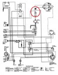
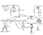
I have attached a diagram, in case you need it.
Thanks guys
On the connector going to the module, I have a ground coming from the ignition coil, and the other wire I am wondering about. It is purple, I believe it is coming/going to/from the alternator.
~~~EDIT I believe This was inacurate.. I may have got my wires crossed tracing them
I can tell you it is not sending 12vpos to the module (hopefully thats what it is supposed to do, and it isn't, and Ive finally found my problem). should it be another ground, should it be 12vpos?
The module also has a separate wire ground to the bracket
I dont understand this circuit at all!
How does the ESA "ground" out the ignition coil? Does it send 12vpos to the neg side of the coil?
If I had to "assume", this would be my best guess...
The purple wire in the connector feeds 12v to the module. The other wire in the same connector is the path used to ground out the coil once the ESA switch is activated, and the separate ground wire feeds the module its ground. Power would come in the purple wire, go to the separately grounded module, and send 12vpos to the ESA switch. Once the switch is activated, the 12vpos goes through the switch, and to the negative side of the coil grounding it out.
Am I completely wrong here?
I have attached a diagram, in case you need it.
Thanks guys
")