


Twhjelmgren28
Petty Officer 3rd Class
- Joined
- May 31, 2016
- Messages
- 85
I decided to throw a topic out there on this; it kind of got buried in another topic of mine and I was hoping someone may be able to help. I have an old Neptune EX120 - engine mounted trolling motor.
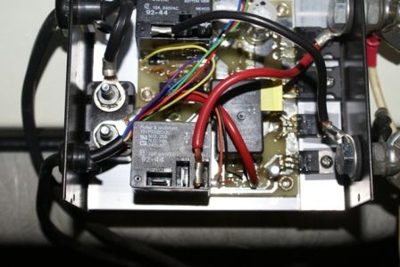
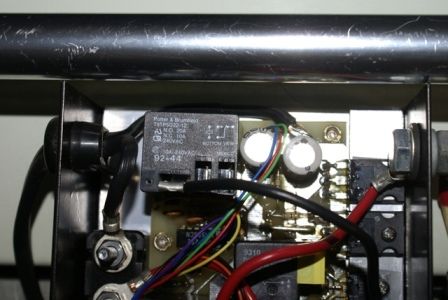
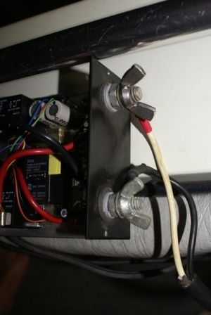
While forward (with variable speed) and off work, when I flip it in reverse, nothing happens. I can hear clicking in the control module but the prop won't spin in reverse. I posted photos below of the control module opened up (I also posted the remote but not the inside of it - I opened the remote up but everything seemed fine, it was pretty basic).
In the photos, you will see two black relays (??); one with a red wire going to it and one with a black wire going to it - in each relay there are three slots to connect the wire terminals. I screwed around with those for a while - in some positions, you could hear the module working but nothing would happen, while in others, forward/off/reverse would all move forward. Also if I put the red wire on the opposite relay, I could get the motor to reverse but then it wouldn't operate in forward...
I know I can get by with forward only but figured I'd give it a shot to try and fix it and/or see if there were any suggestions out there. Any help is appreciated. Thanks!


