Rectifier 1989 Force Outboard

maxum247

Lieutenant
Joined
Sep 18, 2007
Messages
1,363
How do I check for a good rectifier? Book said to set ohm meter to x1 ohm position. My meter has RX1K on it. It will read fine, but my question is will I get the right results set at RX1K is this the same reading as X1? I get good readings on both rectifiers that I have this way. All readings were around 1.5 on each unit. I did my test according to the manual I have. Next question that I have is when I go neg to pos on each I get a reading of 4 on both rectifiers, I know this was not part of the recommended test, but would it give a sign of good or bad. Battery doesn't charge on either one now. Fried a battery and the new one stopped charging or at least I think it did. Battery drains down after about 6 trips and it is started a lot in those 6 trips. Guess my true question is am I going about the test the right way or are the readings I'm getting not as good as I think?
I did AC to +, neg to AC on each of the four poles.
I realized as soon as I clicked the button that this post was in the wrong area.
 

achris

More fish than mountain goat
Joined
May 19, 2004
Messages
27,468
Re: Rectifier 1989 Force Outboard

You should have the meter set to the diode test position. A rectifier is 4 diodes in a bridge configuration. You should test from each AC to the + and - in each direction, 8 tests in all.

The results should be as follows:
Red on AC, black on - should show open circuit
Black on AC, red on - should show about 0.6
Red on AC, black on + should show about 0.6
Black on AC, red on + should show open circuit

If you have at any time connected the battery leads backwards, that will instantly fry a rectifier.

Chris.............
 

maxum247

Lieutenant
Joined
Sep 18, 2007
Messages
1,363
Re: Rectifier 1989 Force Outboard

What will the meter show so I will know if I have an open circuit? Will it not read anything? These are my test results is it good or bad? I'm thinking its bad!
red on ac black on minus, 2
black on ac red on minus, nothing
red on ac black on +, nothing
black on ac red on plus, 2
 

RRitt

Captain
Joined
Mar 30, 2006
Messages
3,319
Re: Rectifier 1989 Force Outboard

it takes 0.7V to turn on a diode. A lot of cheap meters won't even turn them on so they read an open circuit regardless. Trying to read a diode with a resistance setting is usually meaningless. You need a meter with diode setting. --|>|--

If you do not have that then get a 10K resistor from radio shack. They are under a dollar. disconnect all leads. run 12v through resistor and into diode. read voltage across resistor. you should get 12V in one direction since the diode allows electricity to pass through resistor and zero volts in other direction because diode blocks electricity in reverse direction (diode is just like a reed valve except that it is for electricity). check from each output to each input in both directions. that is four checks on each output. If any post gives you zero or 12V in both directions then the rectifier is bad. You can get a replacement from mouser electronics for about $5. Just look for a 35-50A square full-bridge rectifier that looks kind of like the one you have. If it looks close then it is correct one. Bridge rectifiers are required to fit any circuit board from any manufacturer in any country at any time in any piece of electrinics. It is an extremely standardized part. Making a non standard square bridge would be like manufacturing a square tire. No need to worry about voltage ratings. Even the lowest rating is 20x more than you need. Just look for square bridge with 35-50A current rating. By the way - the only special about '89 Force rectifier is the $35 plastic bag that it is packed in.
 

achris

More fish than mountain goat
Joined
May 19, 2004
Messages
27,468
Re: Rectifier 1989 Force Outboard

Maxum,

Your test results are invalid because you used the resistance range on the multimeter, not the diode check function. On the resistance range the meter usually doesn't push enough current for a valid reading.

An open circuit shows on a Fluke meter (and most good meters) as 'OL'. The numbers, like 0.6, indicate the voltage drop across the diode when it is forward biased.

A simple tester would be to run a light globe in series with each diode in the bridge. Use more than 2 volts and a globe of around 5 watts. It should light when the diode is forward biased (current flowing in the direction of the 'arrow' that the diode symbol forms) and not light when reversed biased. Easier to go and buy a meter with a diode check function. Try Radio Shack or one of the local electronics shops.... easier still is to take the rectifier to the shop and ask them to check it for you. :D

Chris............
 

maxum247

Lieutenant
Joined
Sep 18, 2007
Messages
1,363
Re: Rectifier 1989 Force Outboard

I was trying to learn a little about electrical, but I don't under stand electricity! Guess it shows!
Have to go to the shop for boat lettering in a couple weeks I'll take them in and get them checked then. Thanks for all the effort to help me out!
 

JUSTINTIME

Captain
Joined
Sep 2, 2006
Messages
3,284
Re: Rectifier 1989 Force Outboard

best way is get a volt meter, turn it to a/c volts
put leads on battery
start motor
if you get over .8v bad rectifier

do not waste your ti me with diode checks
 

achris

More fish than mountain goat
Joined
May 19, 2004
Messages
27,468
Re: Rectifier 1989 Force Outboard

best way is get a volt meter, turn it to a/c volts
put leads on battery
start motor
if you get over .8v bad rectifier

do not waste your time with diode checks

????????????

This only applies if one of the positive diodes is short. If any diode is open, then you will read 0 volts, which by your test would indicate a good rectifier.

You need to test each and every diode in the rectifier, with a diode test function, to pass/fail a rectifier.

Chris.........
 

JUSTINTIME

Captain
Joined
Sep 2, 2006
Messages
3,284
Re: Rectifier 1989 Force Outboard

1 out it is bad period
this is how we learned in dealers training
you can still test the diodes to make sure
but this test cuts time in half
 

achris

More fish than mountain goat
Joined
May 19, 2004
Messages
27,468
Re: Rectifier 1989 Force Outboard

????????????

This only applies if one of the positive diodes is short. If any diode is open, then you will read 0 volts, which by your test would indicate a good rectifier.

You need to test each and every diode in the rectifier, with a diode test function, to pass/fail a rectifier.

Chris.........

This is how we learned in electronics class as a computer tech. No other way is valid, too many maybe's.
 

JUSTINTIME

Captain
Joined
Sep 2, 2006
Messages
3,284
Re: Rectifier 1989 Force Outboard

on a boat you just keep it simple
now on a computer is a whole different ball game
 

RRitt

Captain
Joined
Mar 30, 2006
Messages
3,319
Re: Rectifier 1989 Force Outboard

I was trying to learn a little about electrical, but I don't under stand electricity! Guess it shows!
Have to go to the shop for boat lettering in a couple weeks I'll take them in and get them checked then. Thanks for all the effort to help me out!

electricity in a wire is just like water in a pipe. If the pipe is broken then water doesn't come out (switch is "off"). If the pipe is complete from end end to other then water comes out (switch is "on", no open circuits). Fat pipes have less resistance and more water flows. Diodes are valves that only let water go in one direction. Transistors are fancy valves that have a control pipe. For each gallon of water that goes through control pipe 20 gallons of water are allowed through main pipe. DC electricity is water that only goes in one direction. AC electricity is water that goes back and forth. Put a diode valve in the pipe and AC electricity will turn into DC. Your rectifier is a fancy set of diodes that not only allows forward water to pass but also redirects backwards electricity. To do this requires four diodes instead of just one. Since diodes are dirt cheap the four-way arrangment (square bridge) is preferred. In some devices (like the wall transformer for your answering machine) there isn't room for four and they still use the single diode valve. The only device left is a capacitor which does same things as a water tower and an inductor which does same thing as putting a very very prop inside pipe. The capacitor sucks up electrons and stores them for later use. The inductor builds up momentum in one direction and tries to keep the water moving.

There ya go. Electricity 101.
 

maxum247

Lieutenant
Joined
Sep 18, 2007
Messages
1,363
Re: Rectifier 1989 Force Outboard

That makes it easier to underderstand, thank you! Went to radio shack and purchased a Full Wave/Bridge Rectifier 25amps/50volts biggest one they had, is this right? Seems I remember 35 amps being talked about. Also remember someone saying that Force rectifiers are rated around 6amps, so if I unerstand the electricity 101 this is way above 6amps, so 25amps should work just as well as 35amps? For reference my outboard is a 1989 Force 125h.p. C model.
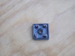
Why the difference in size between the old and new rectifier? I'm thinking the difference in technology today? The new rectifer has a silver metal back, the old one was all plastic, why the difference?
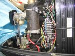
Included are a couple of pictures of the old and new rectifiers, maybe this will help the next guy! Again thanks for the help! I think it's starting to make sense!
 

Attachments

  • Picture 004.jpg
    Picture 004.jpg
    53.3 KB · Views: 0
  • Picture 009.jpg
    Picture 009.jpg
    55.3 KB · Views: 0
Top