I'm looking for instruction for wiring my 40 hp. I think it's a 1960 Evinrude 40 HP. "Big Twin". Model 35520 S# 23821. (If you can check this, or link me to the chart, that would be great).
I'm rebuilding from an old project and I have nothing to go by. The spark is hot on both plugs.
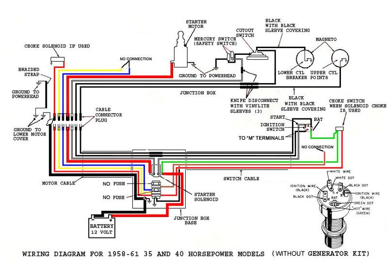
I am converting to electric start, so I'm fabricating new wire harnesses for most of it. I understand (from memory) there is a vacuum / pressure switch on one intake plenum (looks like a fuel pump, except for the wire) that cuts one cylinder in the event of over revving. There also appears to be a "mercury" switch on the thottle assembly to sense WOT or high throttle. I need a diagram of how this is wired so I get the correct cylinder with the switch strategy etc. The rev. limiter seems like a good safety feature to have, in case I shear a prop, or whatever. I also plan to add a tethered cut-off switch. (this is easy, close the two).
I recall reading a page somewhere that described all this in detail. It may have been in one of the shop manuals. If there is a link to that page, or something similar, that is what I would like to have.
All input is welcome, and thanks in advance.
(OBTW: the starter gear seems to only meet half the ring gear. The flywheel is off another motor, and it is the correct shaft dia. Is this OK or do I have something wrong? It looks like it will work fine, just not using as much gear tooth as available). Thanks.
I'm rebuilding from an old project and I have nothing to go by. The spark is hot on both plugs.
I am converting to electric start, so I'm fabricating new wire harnesses for most of it. I understand (from memory) there is a vacuum / pressure switch on one intake plenum (looks like a fuel pump, except for the wire) that cuts one cylinder in the event of over revving. There also appears to be a "mercury" switch on the thottle assembly to sense WOT or high throttle. I need a diagram of how this is wired so I get the correct cylinder with the switch strategy etc. The rev. limiter seems like a good safety feature to have, in case I shear a prop, or whatever. I also plan to add a tethered cut-off switch. (this is easy, close the two).
I recall reading a page somewhere that described all this in detail. It may have been in one of the shop manuals. If there is a link to that page, or something similar, that is what I would like to have.
All input is welcome, and thanks in advance.
(OBTW: the starter gear seems to only meet half the ring gear. The flywheel is off another motor, and it is the correct shaft dia. Is this OK or do I have something wrong? It looks like it will work fine, just not using as much gear tooth as available). Thanks.