Stator question about A/C voltage

Craigbbbbb

Cadet
Joined
Mar 8, 2016
Messages
26
'71 merc 40 stator fails testing procedure in factory manual but still produces 500+ A/C volts when positive lead of multimeter is on green stator wire and negative is grounded out. Is this common for a stator to still produce voltage when it fails factory testing procedure? Checking A/C voltage with a multimeter is not in the factory manual by the way...thanks for any input!!!
 

Craigbbbbb

Cadet
Joined
Mar 8, 2016
Messages
26
I'm not trying to salvage the stator, just wondering more about how a stator works and if a bad stator can still produce voltage, thanks!
 

gm280

Supreme Mariner
Joined
Jun 26, 2011
Messages
14,605
Craig, how did it fail the tests? Explain what you tested and what failed.
 

flyingscott

Fleet Admiral
Joined
Apr 8, 2014
Messages
8,152
Yes a stator can produce voltage and be bad. It can show up as a miss or won't accelerate past a certain point lot of ways to go bad. Sometimes they test good cold and after they get warm it's a different story.
 

Craigbbbbb

Cadet
Joined
Mar 8, 2016
Messages
26
I took a picture but it's over 2mb so I can't upload it.

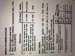
Testing procedure for Merc 40 Thunderbolt ignition single cylinder stator

1. Plus VOA lead connected to green stator lead and negative VOA lead connected to ground ----- VOA range - Rx1000, reading is no continuity

2. Negative VOA lead connected to green stator lead and plus VOA lead connected to ground ----- VOA range - Rx1000, reading is 20-50 ohms resistence

My stator passes the first test with no continuity, and fails the second test with no continuity when the stator should have 20-50 ohms resistence

Wish I could upload the picture of the procedure directly from the manual for you guys!
 

gm280

Supreme Mariner
Joined
Jun 26, 2011
Messages
14,605
Craig, Something doesn't make any sense to me. All you are really doing is testing the stator one direction and then changing the leads and testing in the other direction. If you are reading a stator coil, they should be no read in either direction to ground. If there is, the coil is somehow connected to ground or shorted to ground. That sound more like testing a diode then a coil. But without any further knowledge of what you are doing, that is just my uneducated guess. JMHO!
 

Craigbbbbb

Cadet
Joined
Mar 8, 2016
Messages
26
The coil passes the test in the factory manual, the stator does not, not yet at least. I'll try to figure out how to post the picture of the testing procedure out of the factory manual. Thanks again!!!
 

Craigbbbbb

Cadet
Joined
Mar 8, 2016
Messages
26
Below is the link for the picture with the testing procedure for stator and coil in '71 merc 40 thunderbolt ignition, I'll eventually learn how to compress pictures so the file is small enough for me to post the pic directly to the forum
 

Craigbbbbb

Cadet
Joined
Mar 8, 2016
Messages
26
No Title

Hope this picture is good enough quality for everyone
 

Attachments

  • photo240750.jpeg
    photo240750.jpeg
    274.7 KB · Views: 0

gm280

Supreme Mariner
Joined
Jun 26, 2011
Messages
14,605
Hope this picture is good enough quality for everyone

Okay Craig, I did read the posted picture, but without a schematic diagram showing how that stator is wired and what they are trying to test, It really doesn't mean much to me. If you have a schematic diagram of the circuit, post it and let's see what's up. :noidea:

I have no idea how your stator is wired or what they are trying to determine with that test. :sorry:
 

clanton

Rear Admiral
Joined
Jul 9, 2001
Messages
4,876
You are getting voltage because the stator is shorted to ground. Incorrect testing, voltage output from stator is meter connected to 2 wires, not one meter lead to ground. The test for one meter lead to wire, one meter lead to ground is test for shorted stator.
 
Top