


turtle1173
Chief Petty Officer
- Joined
- Nov 29, 2001
- Messages
- 437
Hi all,
I've been completely redoing my 1971 16' Starcraft Super Sport. It never had a switch panel, everything just ran to the battery. So I'm doing it right this time and putting in a switch panel. I've also put a positive and negative bus bar under the console. This is fairly new stuff to me but I'm good at following directions. So I have some questions and just need a little reassurance that my thinking is correct..
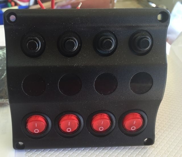
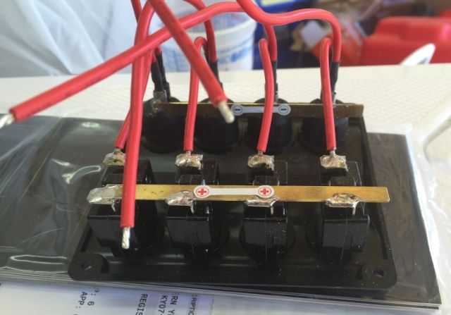
1. The switch panel (pic below) is labeled with a positive and negative side. Then there is a red wire that comes off of each switch. I plan to run the positive and negative wires directly to the switch panel. Is this correct? Then for each device, I have the black wire going to ground and the positive wire going to each switch. Is that correct?
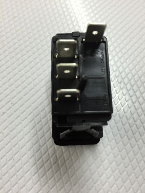
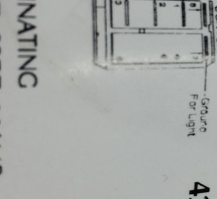
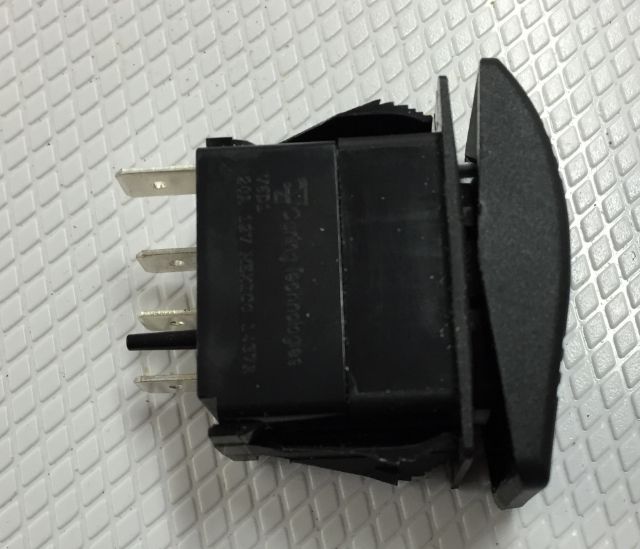
2. The 3 way switch is confusing to me. There are 4 connection spots. See pics below. Where it says "ground for light" and "+12 volt batt", am I just running wires from my bus bar to those terminals (+ and -)? For the top switch, is this supposed to be the front navigation light, the back anchor light, or both? Same question with the bottom switch. Unsure how this is supposed to go.
Thank you so much!
I've been completely redoing my 1971 16' Starcraft Super Sport. It never had a switch panel, everything just ran to the battery. So I'm doing it right this time and putting in a switch panel. I've also put a positive and negative bus bar under the console. This is fairly new stuff to me but I'm good at following directions. So I have some questions and just need a little reassurance that my thinking is correct..
1. The switch panel (pic below) is labeled with a positive and negative side. Then there is a red wire that comes off of each switch. I plan to run the positive and negative wires directly to the switch panel. Is this correct? Then for each device, I have the black wire going to ground and the positive wire going to each switch. Is that correct?
2. The 3 way switch is confusing to me. There are 4 connection spots. See pics below. Where it says "ground for light" and "+12 volt batt", am I just running wires from my bus bar to those terminals (+ and -)? For the top switch, is this supposed to be the front navigation light, the back anchor light, or both? Same question with the bottom switch. Unsure how this is supposed to go.
Thank you so much!


