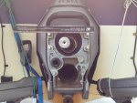
SX Cobra, Gimbal seal removal

89-conv

Seaman Apprentice
Joined
Aug 6, 2011
Messages
48
95 SX cobra, OMC/Volvo-Penta.

Well dang it, I read somebody describing how to get the seal out after the bearing is removed.. But, shoot been hunting for a few hours and I can't find it again..

Seal is to slick, or otherwise to use any pullers.. The manual says to use the same tool that ya pulled the bearing out,, But,, Ha, ha, ha, ha,,,, yeah right,, I tightened the 3 finger puller up on that seal.. so, it ought to have grabbed what ever it could.. all that did was to tear some of the rubber off at each point the 3 finger puller caught on it..

Anybody got a easy plan for getting it out with bellow still on?
 

Don S

Honorary Moderator Emeritus
Joined
Aug 31, 2004
Messages
62,321
Re: SX Cobra, Gimbal seal removal

You just have to get under the edge of the and pry/bend the seal toward the center, then grab with pliers and pull it out.
 

89-conv

Seaman Apprentice
Joined
Aug 6, 2011
Messages
48
Re: SX Cobra, Gimbal seal removal

Yah, thanks Don.. Yup that's just about what I recall having read in another thread, but was hoping I was wrong!..

Dang-it.. That's some tough poking at the sides of that seal while it's got the bellows on. Dark, hard to see, hard to hold a flashlight inside, difficult to get into the side of the metal of seal, ,, and, ain't too many tools lying round that's long enough to get in it,, with enough sticking out the bellows to be able to tap it, to wedge that seal..

shoot..
 

89-conv

Seaman Apprentice
Joined
Aug 6, 2011
Messages
48
Re: SX Cobra, Gimbal seal removal

OH MAN!! Yeah I did that, using an awl to pry the edge up, then a small tipped 2 foot screw driver. Which the metal case is pretty hard steel, so, had to hammer the screwdriver to sink it to the bottom of it. Then following through with a larger tipped screw driver, more hammering to get it down and in. And finally using a 3/4 inch dowel against the cylinder wall the Gimbal bearing sits in, to wedge against the larger screwdriver and push the edges away from the side of the cylinder it's slotted into .

After having to wedge up about a 3rd or more of the sides of the seal it finally came out..

BUT, OH Man,, so much damage on the sides of the cylinder wall where it slots into..


A nightmare scenario with the up pushed areas where the screwdrivers dug into the sides. Now I'm completely frustrated with no concept as to how I'm going to trim those gouged spots back down..??

What a MESS, I can't BeLiEvE, that's the only way to get the seal out,, That's totally nutz.. What were they thinking??
 

bruceb58

Supreme Mariner
Joined
Mar 5, 2006
Messages
30,588
Re: SX Cobra, Gimbal seal removal

This is why I never bother changing that seal.
 

sethjon

Senior Chief Petty Officer
Joined
Jun 8, 2010
Messages
692
Re: SX Cobra, Gimbal seal removal

Take the bellows off.
 

89-conv

Seaman Apprentice
Joined
Aug 6, 2011
Messages
48
Re: SX Cobra, Gimbal seal removal

H,a ha, ha,, whelp guys tell ya what.. THAT's so NUTZ.. AND By the way,, The Shop Manual says ya don't need to take the bellows offf, or nutin..
"Access can be gained by going through the U-joint
belows on an assembled transom shield."
URGH!! insert engineering designers of this out drive, hidden comments: "" Mah, ha, ha, ha!! ah, ha, ha, ha!!!""
!""

However, now with it all off and everything, I took a triple forged tipped screwdriver and curved one side slightly.. then created a little bevel on the other for a long handled chisel, and carefully cut off the high spots fairly well..

Now having done this,, in retro spect it appears that I didn't need to do as much damage to the wall of it as I did..

I'd tilted the screwdrivers toward the wall trying to get deep into the very corner of the seal to pry.

But,, Now I see that, there is a slight beveled edge on the outer rim of the wall,,.. obviously designed so ya can get something in to pry the seal loose.... When I began prying the seal toward the center it looked like, from the dark, gloomy, 10-12 inch distance, inside the bellows that I had began to snap the corner edge of the metal seal, and that scared me into thinking : If that corner edge breaks inside there the back wall of the metal would get even more tighter.. So, that's why I'd angled my screwdrivers toward the cylinder wall of the seal pot.

Once I got it out,, ,, no it was not breaking,, but bending the corner in a good way, so actually, had i kept my screwdrivers at the angle where I'd be driving the edge toward the center of the hole,, consistently, the damage would have been minimal.. at most some scaring on the outer beveled edge.. previously, it was to dirty to be able to see that beveld edge.. , that's to say,, I cleaned it good, but without haveing some experence as to what to expect,, old grease sat in the bevel, and 'who knew'?

Fun, fun FuN!! ha ha..

It aint over,, no sir, this saga just wont stop,, Murphy [Murphy's law] is paying close attention to ev-bery dang move I make..

New thread to follow, installing gimbal bearing,, but, the new seal's inner circular spring likes catching and coming out!
 

Don S

Honorary Moderator Emeritus
Joined
Aug 31, 2004
Messages
62,321
Re: SX Cobra, Gimbal seal removal

New thread to follow, installing gimbal bearing,, but, the new seal's inner circular spring likes catching and coming out!

They always do. Throw it away. That seal is only a dust seal, it doesn't keep water out or grease in. Just the dirt out of the bearing.
 

89-conv

Seaman Apprentice
Joined
Aug 6, 2011
Messages
48
Re: SX Cobra, Gimbal seal removal

Well Heck, thanks for the quick reply Don.

I've been literally shaking with anxiety thinking about that retainer spring..

I figured, last night, why that spring fails when entering through it with the alignment/bearing installation tool.

What I think is happening is; as the edge of the varied tips of alignment tool touches that seal,, if the first edge doesn't push that spring loose the second higher edge will.. So, I've been frightened with the thought that it's near impossible to get it in,, save luck, without one of the two edges in each higher gradient pushing the center of the seal and allowing the spring to come loose,, .. Hence, I've been frightend thinking, ,, without the spring, i'd be increasing the chances of sinking if the bellows cracks and lets water in.. or visa versa, I take on water in the Hull and it goes right through that seal, 'and damages the bearing..

Interesting enough,, I think there's good odds I did not need to change the gimbal bearing, it looks super clean and sharp, PLUS<>> The original seal did have its spring in place.. BTW I have not mentioned, I've got rheumatoid arthritis, and my hands are so twisted,, no way I can get em inside there to have felt the original bearing to see if it was smooth,, just had to assume the worst.. .. fortunately me son is here for a few days currently and his hands can replace that spring,, ha, ha..

I began this little journey because with no doubt, I had a decently loud noise emanating from this area..

I thought either my U-joint was bad, or the gimbal bearing,, But U-joints are sweet, and,, At first I'd bought only the center gimbal bearing,, I was told ya can just knock out the center and replace it easy sleazily,, but,, Ya got to smack the heck out of the bearing's center to get it to pivot.. which I also learned,, BAD advise,, at least in this type of drive,, there's to much wall behind the bearing to get the center to pivot,, 'Maybe Mercs will,, but mine is a no go..

So, anyways, after I'd beat the heck out of the original bearing,, I'd bought an alignment tool off of e-bay..

that's when my suspicion arose because,, I did not have any trouble removing my drive,, slide out pretty easy, and only caught on the edges of the bolts.. So, I figured it's aligned pretty good, based on the other topics I'd read before I started..

But, while the old bearing was in, abet damaged,, When I slid the alignment tool in, I was not able to get it to slide into the coupler spline.. no way ..


I was able to pivot the bearing to move it around,, so,, I figure it was still seated OK.. but still couldn't get it to slip into the spline.. Once I'd taken the bearing out,, although I'd damaged some of the caseing,, the bearing i smooth.., so, I think it was fine after all.

With the bearing and seal out,, a test run of the alignment tool, showed,, nothing wrong inside the spline as it slid in just fine..

So,, my next topic, obviously, two things..

1. If I couldn't get that tool into the spline,, assume it's really really misaligned, and do what?? All I can think of for now is,, 'eyeball it close?,, ecept the drive came out so easy,, I'm thinking, it's not it but, my ignorance..

I'm sure the noise was comming almost directly from the gimbal bearing area,, although I did not think to check from the inside of boat at the time.. regardless by useing a long screwdriver's handle tight to my ear,, pretty much narrowed down, noise in that place..

2. or actually most important,, should be 1.. If my bearing was fine, u-joints fine,, so far the inspection of the coupler looks fine,, splines decent,, and I can't see any rubber ripped or mangled around the spline.. Could the noise which was emanating from the gimbal bearing area,, could a really bad alignment have caused the noise?

I've good great concern at this point, because, I've no way to insure the drive is actually close enough in alignment, and if it is really really out,, when I try to install the bearing,, with the alignment/bearing installation tool.. it ain't gonna slip into the spline, and therefor damage it as the bearing is hammered in..

According to the instructions on mounting the bearing installation tool on the alignment shaft,, Sposato inset the shaft all the way into the spline,, mark the spot where the outside edge of bearing sits,, then take off 1/4 inch and Mount there.. which means,, it's got to slid into the spline as the bearing is hammered in.. ugh..


***-U-Me, hate that word, lol.. except it seems appropriate when ignorant is playing with mechanical stuff, he/she's never done before.. Autos I good,, real good, but, besides repairing a rope on an outboard 40 years ago,, zero experience in boats!! lol.
 

89-conv

Seaman Apprentice
Joined
Aug 6, 2011
Messages
48
Re: SX Cobra, Gimbal seal removal

Yes thanks Don, I have read that,, in fact read it a few times,, as when my old bearing was still inside,, as I said,, i could not get the alignment tool to slide into the spline,, I knocked it around all kinds of ways, according to the instructions on that page. and as I said,, the bearing pivoted just fine,, just would not pivot to an angle where the alignment tool could get into the spline..

So,, what I'm trying to discover is,, before I attempt to install the new bearing,, how can I get my engine aligned as close as possible?


I am thinking that maybe I can reset the bearing installation tool on the shaft, as close to the tip as the shaft will alow and still be on the largest area.. to get the bearing in, verses the recommended spot which obviously,, if I can't get that shaft into the spline as I hammer the bearing in... it's gonna beat the heck out of the coupler..
 

89-conv

Seaman Apprentice
Joined
Aug 6, 2011
Messages
48
Re: SX Cobra, Gimbal seal removal

Here's a photo of the alignment shaft,, with the drive centered as best I could,, seal is installed but, gimbal bearing is currently out still. .. showing how far out of alignment the engine seems to be currently.. View attachment 123341 The engine is shifted toward the right side.. as the tool is angled to the left.. And as it's dificult to get a good photograph,, it it looks more out toward the left and sligtly down than the photo shows.. another photo,, ; 2alignment shaft off center.jpg maybe "Mayvbe' as I've really tried hard to center the camera in this one,, regardless maybe slightly exaggerated left, but ya should get the idea.. engine is shifted sideways

I do not see a way to move the engine sideways.. ?? The shop manual does not have a word to indicate sideways ajustment, only up or down,,..

So, obviously if I were to attempt to drive the bearing in, at this point, I stand a good chance of not getting the shaft into the coupler, and blindly damaging it as the bearing is pressed/hammered in.. ..

I can't see anything wrong with the front or rear motor mounts,, rubber looks and feels sound, clean. Can't find any damage on the drive plate inside or out.. No visible indication the plate has shifted, but I am sure it was the sideways shift which was why I could not get the alignment tool, [as mentioned earlier] to slide into the coupler when the original gimbal bearing was still in,, I could see that was off center to the right..
 

Don S

Honorary Moderator Emeritus
Joined
Aug 31, 2004
Messages
62,321
Re: SX Cobra, Gimbal seal removal

So,, what I'm trying to discover is,, before I attempt to install the new bearing,, how can I get my engine aligned as close as possible?

Stop wasting your time and over-thinking this job.
Put the gimbal bearing in and then do the alignment. You are accomplishing nothing without the bearing in there.
 

89-conv

Seaman Apprentice
Joined
Aug 6, 2011
Messages
48
Re: SX Cobra, Gimbal seal removal

Yes, I discovered that, the spline has a decent bevel where ya can fit the alignment tool into it
and force the coupling's center over while inserting the bearing.

So, I jammed the bearing in after all. Carefully leaning toward the side I figure is off. and once I was sure I'd entered the spline/coupling seated the bearing proper.

However, I can't get it into alignment,, I've gone up, down and attempting some sideways action by lowering or raising one side of the front mounts, or the other..

I've also smacked the bearing at 90 degree angles as shown in the thread ya posted,, three to four different times, Because:

What's happening is: the right side of the alignment bar is touching the spline, while, no mater which way I move the motor mounts,, the whole left side wont leave a mark..

I can see that the splines are fine, none missing..
 

Don S

Honorary Moderator Emeritus
Joined
Aug 31, 2004
Messages
62,321
Re: SX Cobra, Gimbal seal removal

Put the gimbal bearing in, and start the alignment process like it was a new installation and you were starting from scratch. This is not something that is learned by reading posts in a forum. You can read what has to be done, but then you have to actually do the job and it may take many trips in and out of the boat if you're doing it yourself.
If you can't figure it out yourself, then it's time to find a marine shop. Either Volvo or a Merc dealer. I wouldn't bet any of the independent shops can do it. Most are auto techs looking for easy money and don't have a clue.
 

89-conv

Seaman Apprentice
Joined
Aug 6, 2011
Messages
48
Re: SX Cobra, Gimbal seal removal

Put the gimbal bearing in, and start the alignment process like it was a new installation and you were starting from scratch. This is not something that is learned by reading posts in a forum. You can read what has to be done, but then you have to actually do the job and it may take many trips in and out of the boat if you're doing it yourself.
.

Yes, this is about what I've been thinking.. have to take it to start and begin zeroing it in.. But where to start?

The manual does not say anything to this effect. It just says, basically; stick the engine in and align up or down..

Obviously I've got a sideways adjustment to do..

If it's any consolation Don, While I've never worked on a boat. I have zeroed in large electrical motors to coupling shafts. When a electric motor is out of alignment to whatever shaft it's mounted onto, its tail will waggle, and eventually ruin the motor bearings. But,, it's not exactly the same because you don't have a transom blinding ya, lol..

I am thinking, that,, I can shift the engine very slightly from side to side, by either moving up or down the front engine mounts independent of each other verses in union. .

But, at this current stage, yes, I don't have a clue as to where to set the mounts and start..

I know that, were I to raise the left mount, only, it would tweak the engine slightly to the left while obviously lowering the coupler,.. As, The rear mounts appears to be set to the plate, non-adjustable. so, the rear mounts act as the pivot point..

I tried raising and lowering just one side mount at a time, to see if I could get the spline to touch the left side of the alignment tool,, but,, there was not much difference gained, ..

So, basically, if ya could just point my nose, where to read,, where to set the mounts to start,, etc.

I've got my son home for two more days,,, lol.

we been hoping to see if my fiberglass driveway log actualy foats while he's here, ha..
 

Don S

Honorary Moderator Emeritus
Joined
Aug 31, 2004
Messages
62,321
Re: SX Cobra, Gimbal seal removal

The engine is not adjustable side to side, only up or down. If your alignment was good before, changing the gimbal bearing does NOT change the alignment. You might try turning the engine 90, 180, and 270? see if it changes.
 

89-conv

Seaman Apprentice
Joined
Aug 6, 2011
Messages
48
Re: SX Cobra, Gimbal seal removal

Revisited; all this time I'm just looking at a fiberglass driveway log.. Since last discussion here,, I said the engine is out of alignment.

Can measure the off set angle of how far sideways, vertical, it's off, while the alignment tool is inserted, distance off center.

I've discovered that, the motor mounts are adjustable sideways. mounted with two lag bolts each mount has a rear lag bolt hole which is small and unadjustable. While the front hole is oblong and the engine can be moved sideways in either direction,, the rear none adjustable hole acts as a pivot.. there's actually enough to move the engine about 1/4" inch one way or the other without having to reset the lag bolts,, go figure??.

With that said in my case, using this range to adjust it's not enough..

To find center of the front of engine to boat, measuring the distance from the inside of hull off of the center of harmonic balancer, which is also center of the crank shaft. Before attempting any adjustment the engine was 7/8" off center toward the right side of boat..

I said before that I could not get the alignment tool to touch the left side of the couplers spline/groves. That is when the alignment tool was removed, it had not touched the spline or left any marks in the grease on the whole left side..

Rotating the engine at 1/4 intervals, also caused me to readjust the up/down, horizontal pivoting of mounts.. and never showed the spline touching the left side..

Rotating and having to readjust horizontal pivots nearly every time caused me to be concerned that the coupler might be bent..


However,, it's difficult to get any type of potential reading if the coupler is bent.. Moreover In my opinion accuracy and zero center, while the engine's crank shows that; the front of engine, in relation to the inner sides of the hull is off center 7/8", and possibly as much as a whole inch.. In my experence finsih work that's 7/8" off is a dang INCH! LOL

That's tremendously disturbing!.. The mounts are original,, factory set, and have never been adjusted or moved,, they are clean and rubber is like new...

I've moved the front of engine over with all lag screws removed now. And at this time I've extended the distance well beyond any possibility of using the original holes they were set in..

It's currently 3/8" off center now,, the engine,, this has caused the ability to just about get butter on the alignment tool.. and now it's just touching that left side grease, yet not balanced enough to obtain equal amounts of spline touch on both sides of the tool..

'Almost' butter..'

Obviously adjusting the engine sideways has caused an improvement in the center alignment between engine and drive transom housing, which incidentally, the transom drive housing/mount unit, 'exterior' is vertically centered dead on..

But that's the whole problem!!

How could the factory have missed centering the front of engine by up to 1 WHOLE INCH!??

1996 4 winns.. The mounts are on a molded ledge specifically designed for them.. out riggers, as it were.. Appear to be well built, with a wood core, and fiberglass molded covering sealed into the bottom of hull..

looking at these 'ledges' the factory holes appear to be centered equally in them.. they are clearly molded which, in my mind says; there's no way these ledges could possibly be off center.. and with the engine in and all, it's practically impossible to find their distance to center and verify that they are or not.. ..

But,, measuring center, and I'm using a level to insure I'm getting a accurate dead on center figure of the crankshaft between the inner sides of the hull,, there's ya go, almost 1 inch off center factory set..

How could that be.??

it's why I'm sitting on a driveway log unable to complete installing the rebuilt drive...

I haven't the boating experience, while I've been repairing engines since I was a child,, not the experience in boating to understand how or why,, those molded ledges could be wrong? or I'm just an idiot and the engine does not need to be vertically centered inside the boat??

Now If I accept for some reason,, those molded mounts could be manufactured way off,,, I'm also a rough and finish Carpenter too, and NOBODY unless drunk misses a hole inch in framing much less finish, which is what those ledges would be,, finish, 1 whole inch oFF!!??

Ok, anyways, if you could imagine,, at this stage,, and if I accept the mount ledges are wrong, if somebody could explain why or how that could happen 'please?

the once this is done,, whenever anybody just looks at them,, they will from then on 'just' look, messed up.. 'like' the mounts are sitting on the ledges way off.. it'll be a aesthetic appearance of something seriously out of balance.. moreover general apearance of a cheaply manufactured boat.

To be expected??,, and or can somebody explain how it could be this far off.. or like I said,, The front of the engine does not need to be vertically centered to the drive transom bracket?
 
Top