system check wiring diagram

Status
Not open for further replies.

chillinjc

Cadet
Joined
Aug 2, 2003
Messages
11
My wife had her heart in the right place, found me a new guage on ebay for a johnson, only problem is it has system check type termin on the back (8 pin). Now I have a 92 johnson thats running great, but I would love to se this guage. does anyone know where I caan buy a harness for it? (only to use tach, and guage light not sys check) or does anyone know the wiring configuration, pin layout label or have a diagram for it. I may be able to make my own harness that will work with old three pin harness if I knew the schematic. (im a PC tech) I need to know what pins do what or where to get at very leat a cheap extension harness with female plug end to experiment with email me at chillinjc@hotmail.com or please leave a line! :confused: :( chillinjc@hotmail.com
 

seahorse5

Rear Admiral
Joined
Jan 24, 2002
Messages
4,698
Re: system check wiring diagram

There is an adapter kit, not cheap, that can convert older motors to use the System Check. You have to have a 4 wire VRO pump for it to work.
 

chillinjc

Cadet
Joined
Aug 2, 2003
Messages
11
Re: system check wiring diagram

I would love to know where to get one, any site or do i find my local dealer and aproximate cost! thats the best info anyone gotten to me Thanks please keep posting!
 

jegervais

Chief Petty Officer
Joined
Jan 18, 2002
Messages
646
Re: system check wiring diagram

The adapter harnes lists for around $230.<br /><br />If you just want to use the tach function of the gauge, here's the pin configuration (looking at the back-side of the gauge, holding it upright):<br /><br />1-2-3-4<br />8-7-6-5<br /><br />Purple wire goes to pin 1<br />Black wire goes to pin 2<br />Gray wire goes to pin 3<br /><br />-John
 

chillinjc

Cadet
Joined
Aug 2, 2003
Messages
11
Re: system check wiring diagram

John you ARE THE MAN! :D <br />Thank you! thats what I needed!<br />If ever in the NY area let me buy you a drink! :cool: <br />no chanse you know the other pins is their? I could use the lights for other stuff!
 

jegervais

Chief Petty Officer
Joined
Jan 18, 2002
Messages
646
Re: system check wiring diagram

Grounding these pins, will activate the following:<br /><br />Pin 4, turn on no oil lite<br />Pin 5, turn on low oil lite<br />Pin 7, turn on check engine lite<br />Pin 6, turn on hot lite<br /><br />Pin 8, is used to activate the warning horn, it supplies a ground to the horn circuit when any other warning circuit (pins 4 thru 7) is grounded.<br /><br />-John
 

FishhawkNWO

Cadet
Joined
Jun 11, 2022
Messages
9
Hello everyone, I purchased a boat last summer and started it for the first time yesterday after sitting all winter. It has a 1996 evinrude 50hp with the same tach system check you guys are speaking of.

I noticed the tach wasnt working and came to find that it was unplugged. While plugged in the motor would not start. With it disconnected it ran fine. After plugging it in again the tach got so hot it melted pin 1 and it pulled out from the gauge when I went to remove the connector.

After checking voltage on the connector side l, with the ignition in the on position there is 12V being supplied to pins 1,4, and 8. Is this normal? Should these pins have power at all? Truly at a loss and now need to send the tach in for repair. Previous owner said he didn’t know anything about it.

Thank you in advance
 

Chris1956

Supreme Mariner
Joined
Mar 25, 2004
Messages
28,074
Pin 1 is purple wire, should have ign +12VDC

Pin 2 is black wire, ground all the time

Pin 3 is grey wire, is tach sender

Pin 4 is tan/yellow from VRO pump, should not have voltage. Should ground to indicate "no Oil" alarm

Pin 5 tan/black is low oil in reservoir. Will ground when low oil.

Pin 6 -Tan- is overheat, Will be grounded when engine overheats.

Pin 7 is tan/orange. Is "system Check" alarm. indicates fuel restriction on V6 OBs only.
Pin 8 is tan/purple, will supply voltage to horn. Probably if you fix pin 4, that will get fixed.

So I would look for melted wires near VRO pump, allowing purple to short to tan/yellow
 

FishhawkNWO

Cadet
Joined
Jun 11, 2022
Messages
9
Pin 1 is purple wire, should have ign +12VDC

Pin 2 is black wire, ground all the time

Pin 3 is grey wire, is tach sender

Pin 4 is tan/yellow from VRO pump, should not have voltage. Should ground to indicate "no Oil" alarm

Pin 5 tan/black is low oil in reservoir. Will ground when low oil.

Pin 6 -Tan- is overheat, Will be grounded when engine overheats.

Pin 7 is tan/orange. Is "system Check" alarm. indicates fuel restriction on V6 OBs only.
Pin 8 is tan/purple, will supply voltage to horn. Probably if you fix pin 4, that will get fixed.

So I would look for melted wires near VRO pump, allowing purple to short to tan/yellow
Thank you so very much!! Will do as you suggested and report back. I am not sure however if this motor has “VRO”?
 

Attachments

  • image.jpg
    image.jpg
    1.9 MB · Views: 8
Last edited:

racerone

Supreme Mariner
Joined
Dec 28, 2013
Messages
38,415
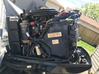
The VRO pump is clearly visible.-----But it is up to the owner to determine if it is in service or bypassed.----Perhaps have a shop check it out.----Or run with 50:1 in your fuel tank and see if oil level goes down in the oil tank !!
 

FishhawkNWO

Cadet
Joined
Jun 11, 2022
Messages
9
The VRO pump is clearly visible.-----But it is up to the owner to determine if it is in service or bypassed.----Perhaps have a shop check it out.----Or run with 50:1 in your fuel tank and see if oil level goes down in the oil tank !!
It is not bypassed, I will do some more reading though thanks for the info
 
Status
Not open for further replies.
Top