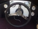
Just wired up the new gauges so that I could finally find out what my Revs are for peace of mind before i send the boat to get stripped down.
Anyway, Tach is great, shows a max ever of 5200 RPM and the speedo bounces between 55-65mph.
The temp gauge is showing readings of right when i turn it on 160 and when idling about 200, when going for it, nearly off the clock.
No overheating horn, i have heard the horn before when nearly out of gas and WOT, it went off. Before i put these in. So when i put this temp gauge in, I just used the same wire sender that was on the last one.
It is obvious that it is wired wrong to me, if it is not then i have a problem i need to address.
Photos, and what each is. Hope they upload in order.
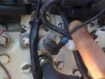
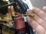
1. This is the wire that is plugged into my temp gauge as 'Sender'. (seems to me to be ground?) IMG-0230
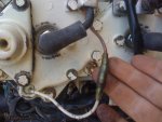
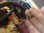
2. what i imagine to be the right wire to be plugged into sender. IMG-0231
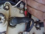
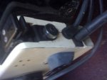
3. same thing but other side. IMG 0234
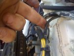
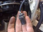
4. where those tan wires go. IMG 0236 and IMG 0235
NEXT POST PHOTOS
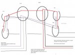
5. one tan wire then comes out of the mix?? Where is the other one?
6 where all those joined wires lead to (OMC)
7. Something else that si a mystery to me (maybe off the VRO unit?)
Anyway, if you guys could please help me try and figure this out without having to spend another $500 taking it to the mechanics would be great.
My big questions are, why is the tan wire out of the mix before the plug? I asked the mechanic and he did not know thinking it was off the VRO or something. I pointed it out to him the other day while doing the rectifier, now it looks obvious as to what it is.
Also, where has the other wire gone without having to cut open the tubing of wires to find out?
Is the black one the ground?
is my temp reading the corect temperature? if not, how is it reading at all if that is a ground wire?
Thanks for your time.
Anyway, Tach is great, shows a max ever of 5200 RPM and the speedo bounces between 55-65mph.
The temp gauge is showing readings of right when i turn it on 160 and when idling about 200, when going for it, nearly off the clock.
No overheating horn, i have heard the horn before when nearly out of gas and WOT, it went off. Before i put these in. So when i put this temp gauge in, I just used the same wire sender that was on the last one.
It is obvious that it is wired wrong to me, if it is not then i have a problem i need to address.
Photos, and what each is. Hope they upload in order.
1. This is the wire that is plugged into my temp gauge as 'Sender'. (seems to me to be ground?) IMG-0230
2. what i imagine to be the right wire to be plugged into sender. IMG-0231
3. same thing but other side. IMG 0234
4. where those tan wires go. IMG 0236 and IMG 0235
NEXT POST PHOTOS
5. one tan wire then comes out of the mix?? Where is the other one?
6 where all those joined wires lead to (OMC)
7. Something else that si a mystery to me (maybe off the VRO unit?)
Anyway, if you guys could please help me try and figure this out without having to spend another $500 taking it to the mechanics would be great.
My big questions are, why is the tan wire out of the mix before the plug? I asked the mechanic and he did not know thinking it was off the VRO or something. I pointed it out to him the other day while doing the rectifier, now it looks obvious as to what it is.
Also, where has the other wire gone without having to cut open the tubing of wires to find out?
Is the black one the ground?
is my temp reading the corect temperature? if not, how is it reading at all if that is a ground wire?
Thanks for your time.