Total re-wire questions

Degrath

Seaman
Joined
Oct 6, 2016
Messages
53
I am wanting to do a re-wire of my 1974 Caravelle. Current setup is a mess, all kinds of random wires of random types (lamp cord, speaker wire, Bare wire) some go places others don't. I didn't wire it this way, previous owner(s) added and deleted items with whatever wire they could find apparently. No Fuses No circuit breakers anywhere!
From the battery I have a hot and ground running forward to power the lights, horn, and gauges there are separate wires for the bilge pump switch. everything is hot as long as the battery hooked up.
The outboard harness runs up separate to the ignition which has nothing wired to the accessory (On) position and 3 wires from the harness hanging loose. Orange(temp), purple(tach), and black(ground).

I am working on a wiring diagram now to clean things up and allow for easy troubleshooting in the future. I plan to add some missing gauges, a radio and some interior lighting in the future as well
1. What should I feed from the Accessory position on the ignition? I would like to have everything dead except the nav/anchor lights and the bilge pump without the key
2. The ground in the outboard harness currently hanging loose, Do I use it to ground the gauges and accessories up front and remove the ground coming forward straight off the battery?

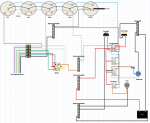
I have attached what I have so far on my drawing. I am using MS excel but converted to pdf so I could attach it. Please let me know if Im on the right track. Thanks in advance!
 

Silvertip

Supreme Mariner
Joined
Sep 22, 2003
Messages
28,771
The only thing that should feed from the "A" (accessory) position on the ignition switch is the instruments. Likewise, the ground in the engine harness is for instruments. Rarely is this ground used for other items. You need a separate #8 or #10 pair of wires running from the battery to a fuse panel wherever you wish to place it. All switches and the circuits they control are then fed from the fuse panel. A 20A breaker must be installed in the positive lead within a foot of the battery to protect the circuit from the battery to the fuse panel. All circuits fed from the fuse panel need fuses or breakers sized appropriately for that circuit. Most current fuse panels have a ground bus integrated into them so all grounds connect there. Bilge pumps, livewell pumps and other stuff located at the back of the boat can be connected to a separate ground bus located in the vicinity of those items. If you want to kill everything, one of the switches on the console can be used as a MASTER. It would be connected in the +12 volt feed from the battery and essentially turns the fuse panel on and off.
 

Degrath

Seaman
Joined
Oct 6, 2016
Messages
53
Thanks a bunch, I was thinking along the same lines but wanted to be sure. I have nearly finished my wiring diagram and that is the route I went. Using the A and the ground off the ignition for the instruments only with a separate positive bus running from the battery with breakers. I just kept thinking of how much current would be drawn thru that old harness if everything was pulling 12v off of it. A fire waiting to happen... Now if I am using 7 pin led rocker switches the +V from the ignition is safe to run to those as well as 12v from the positive bus on the battery?
 

Silvertip

Supreme Mariner
Joined
Sep 22, 2003
Messages
28,771
Do not run two separate 12 volt circuits to the switches. The switches and their LEDs would be powered from the separate feed from the battery -- therefore no need to have the "A" terminal feed as well.
 

Degrath

Seaman
Joined
Oct 6, 2016
Messages
53
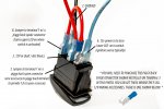
Switchwiring.jpg
so this is not a good thing on the LED rocker switch?
#2 says source with inline fuse? I am assuming 12v from battery
#3 says relay or ACC which is the ignition?
 

Degrath

Seaman
Joined
Oct 6, 2016
Messages
53
I just noticed my pdf error, I will try it as a png. This is what I have so far, still adding and tweaking. I want clean as possible with the ability to expand it later
boatwiring.png
 

Silvertip

Supreme Mariner
Joined
Sep 22, 2003
Messages
28,771
No. All switches have power IN from the fuse panel. Pin 3 is the "LOAD" or OUT sude of the switch. It feeds a pump, lights, or other accessory. It dies not connect to "A" on the ignition switch.
 

Silvertip

Supreme Mariner
Joined
Sep 22, 2003
Messages
28,771
I just noticed my pdf error, I will try it as a png. This is what I have so far, still adding and tweaking. I want clean as possible with the ability to expand it later

You have no fuse panel and no fuse in 12 volt feed from the battery.
 

Degrath

Seaman
Joined
Oct 6, 2016
Messages
53
You have no fuse panel and no fuse in 12 volt feed from the battery.

I am getting there, still adding. I need to go buy it so I know which one I am wiring for. I ordered the switches and buttons already so I know what their wiring looks like and was able to add it to my drawing.

No. All switches have power IN from the fuse panel. Pin 3 is the "LOAD" or OUT sude of the switch. It feeds a pump, lights, or other accessory. It dies not connect to "A" on the ignition switch.

yes sorry #3 goes out to the accessory.
#6 is the one I meant, it goes to the dimmer or light switch. I just thought because it is a separate circuit working independent from the switch itself getting 12v from the ignition wouldn't hurt. when the key is on the backlight LEDs are on. The switches have a second LED which is active when the switch is in the on position which is jumpered to the 12v battery source.
 
Last edited:

Silvertip

Supreme Mariner
Joined
Sep 22, 2003
Messages
28,771
If you are using this style switch for NAV lights, are you aware that both the bow and stern lights must be on when underway. If stopped, only the anchor light must be on. Other boaters need to know whether or not you are moving. This style switch doesn't appear to support that type of operation unless you use two separate switches but I can't tell that with no part number or manufacturer info. Fuse panels are very generic. You have a +12 volt feed in, perhaps a built-in ground bus and multiple, fuse outputs.
 

Degrath

Seaman
Joined
Oct 6, 2016
Messages
53
I have a 3 pos switch for the Nav lights, it is an On-off-On rocker with 2 independent LEDs, Same for the bilge pump, the horn is a LED push button and the rest are On-Off style rockers.
 
Top