volt testing power packs....

nogo

Cadet
Joined
Aug 15, 2006
Messages
20
is it possible to test power packs with a standard multi-meter (and how if anyone know) or do you need some special omc meter?
 

jtexas

Fleet Admiral
Joined
Oct 13, 2003
Messages
8,646
Re: volt testing power packs....

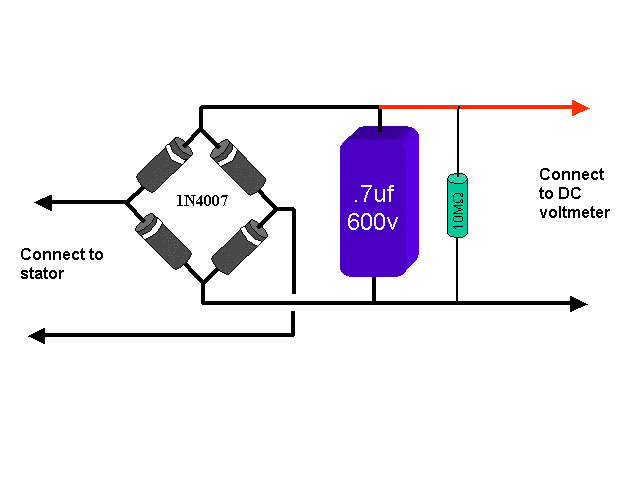
You can measure powerpack output with a multi-meter and a DVA (direct voltage adapter) - you have to measure peak AC.

I have a schematic here for fabricating a DVA which I got from iboats member Paul Moir, but haven't got around to making it yet, really just a full-wave bridge rectifier with a smoothing capacitor:

peak.gif


set your multimeter for DCV - output from stator to powerpack and from powerpack to coils should be neighborhood of 150V at cranking speed. Can't check the trigger output with this one though because of the 1.4v voltage drop...trigger output is around .5 volts peak AC.
 

Xcusme

Commander
Joined
Apr 21, 2003
Messages
2,888
Re: volt testing power packs....

On the CD power pack, you can check the DC voltage output to the primary side of the coils. Connect your DVM, Red lead to anywhere on the power head , Black to the ungrounded lead from the kill button. You'll be reading the DC voltage of the power packs capacitor. This voltage can vary and depends on the A/C voltage from the charge coil (after it's rectified inside the power pack), but typically 150 to 225 volts DC.
 

jtexas

Fleet Admiral
Joined
Oct 13, 2003
Messages
8,646
Re: volt testing power packs....

xcusme, that is pretty amazing...why you never told me this before? voltage from the capacitor...it'll be a pulse, right? Is that a pretty reliable measurement, or more of a yes/no kind of thing?

thanks!
 

Xcusme

Commander
Joined
Apr 21, 2003
Messages
2,888
Re: volt testing power packs....

Nope, no pulse...it's smooth DC voltage. Basically the CD power pack is a very simple circuit. The A/C voltage from the charge coil (under the flywheel) is rectified into DC voltage and stored in the capacitor. The B+ side of the capacitor is really connected to the whole power head (that's why you place your Red meter TO the power head). The black wire coming from the power pack that gets connected to the power packs mounting bolt is not a 'ground' as is commonly thought. It's the DC output of the capacitor. OMC is using the whole power head as a common 'conductor' to get the voltage over to the coils. Since the coils are directly mounted to the power head , that's where they get the voltage for the primary coil winding voltage. This makes a good point to be sure the connections , mainly that little black power pack wire and the coil mounting bolts be clean and tight.

The small coil wire, (what i call the 'back side' of the primary coil winding) gets momentarily connected to the negative side of the cap thru the SCR ,and the coil fires.

The cap. is storing approx. 150-225 volts DC. The whole motor (and aluminum boat !) is charged to this same voltage. Placing the Black meter lead on the ungrounded lead of the kill switch (negative side of the cap) allows you to read the caps. charged voltage. This meter reading is DC voltage.
You can connect your Red meter lead to the small wire on the coils too. This is the 'back side' of the coils primary lead and should show the caps B+ voltage.

Now , this explains how the kill button works. One side of the kill button is connected to the power head ( remember this isn't 'ground', it's 150-225 volts DC from the positive side of the cap). The other kill button wire goes into the power pack , and is connected to the negative side of the capacitor. Since the kill button is Open Circuit ( not internally connected) , the cap can charge up and power the coils. When you push the kill button, the cap is directly shorted ( both ends connected) . Since the cap can't store it's charge with both ends shorted, there's no voltage...thus, no spark to the coils....and the motor dies.

Sorry for the long winded explaination...:^

"Is this a reliable measurement" , you bet ! You can measure the output of the charge coil, and ignition capacitor. Of course, watching these voltages, and their fluctuations, is easier with a scope.
 

jtexas

Fleet Admiral
Joined
Oct 13, 2003
Messages
8,646
Re: volt testing power packs....

That's a good analysis, I for one appreciate it. Looking at the diagram it seems so obvious. Well, not obvious exactly. I always thought of the cap charging and discharging...but...I guess the coil primary takes a lotta voltage but small current...need to give that one some thought.
 

Xcusme

Commander
Joined
Apr 21, 2003
Messages
2,888
Re: volt testing power packs....

Let me digress just a bit, the caps voltage will rise and fall as it charges and discharges. The amount of discharge should be determined by the primary coil impedance and SCR (which is in series and basically insignificant). Since the primary coils resistance is very low, the cap will see an almost instant short to ground through the SCR, and the voltage should take a nose dive. That's why I mentioned the fluctuations being easier to see on a scope.
 
Top