What does this symbol mean in manuals/parts catalogues?

Onegazza

Seaman
Joined
Feb 5, 2019
Messages
65
Hi,

I've seen this symbol in several manuals and parts catalogues by several manufacturers also. Searching it on Google couldn't recognise the image.

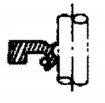
It's used where there is an oil/water seal and I presume it identifies the orientation of the seal. However, what identifies what in the attached example?
 

Attachments

  • photo324006.jpg
    photo324006.jpg
    83.1 KB · Views: 1

alldodge

Moderator
Staff member
Joined
Mar 8, 2009
Messages
42,612
This may help to determine direction. Where it list bearing side replace with fluid side.

Seal-analysis-pays01.png
 

Texasmark

Supreme Mariner
Joined
Dec 20, 2005
Messages
14,780
Just a couple of comments: You don't want the spring on the environmental side is a clue, having the flat steel on the environmental side helps to protect the component. On things like prop shafts, installing 2 seals back to back you protect from water entering and just as importantly, oil leaking out.

I too find the notation confusing until you realize what it represents...20-20 hindsight I guess....after the two prompts you guys posted.
 

Onegazza

Seaman
Joined
Feb 5, 2019
Messages
65
So, what does the example symbol I showed actually depict?

a) assuming the straight line depicts a separation? between 2 parts?
b) what does the "J" mean?
c) if you only saw that symbol, what does it tell you?
d) the two rounded shapes mean a seal each?
 

Onegazza

Seaman
Joined
Feb 5, 2019
Messages
65
(adding that whilst I've taken photos of the orientation of the old seals, that doesn't necessarily mean they were the correct way round, hence trying to understand what the manual means)
 

alldodge

Moderator
Staff member
Joined
Mar 8, 2009
Messages
42,612
So, what does the example symbol I showed actually depict?

a) assuming the straight line depicts a separation? between 2 parts?
It's a drafting line indicating the center line of the shaft

b) what does the "J" mean?
The J is the lip seal which has been cut to show inside the part

c) if you only saw that symbol, what does it tell you?
d) the two rounded shapes mean a seal each?
The J symbol shows which direct the lip of the seal goes. Unsure of the "two" round shapes, but the one small one is the spring which is inside the lip of the seal, the 2 on top and bottom of the shaft is a drafting depiction of the cut away of the shaft
 

GA_Boater

Honorary Moderator Emeritus
Joined
May 24, 2011
Messages
49,038
The drawing in the first post is for a double-lip seal.

dlip.png
 

Onegazza

Seaman
Joined
Feb 5, 2019
Messages
65
Is a " picture " not worth a thousand words anymore ?

Not when you really can't understand what it's trying to show.

Despite the assistance, I still don't understand it.

The two rules in taking away:

1. The spring should face the bearing side I.e. inside of the component.

2. In the case of a double seal, they go back-to-back so, the outside seal is actually facing the "environment" and the inside seal is facing the component.
 

alldodge

Moderator
Staff member
Joined
Mar 8, 2009
Messages
42,612
My previous comment was
Where it list bearing side replace with fluid side.

While the lip would face toward the bearing side but also the fluid side. The lip faces toward what your trying to keep IN. Now in some cases there is a double seal (not double lip seal), where 2 different lip seals are used. In this case for example, one keeps seawater out (lip faces toward seawater) and the other faces opposite the other seal toward the drive lube.

Appears you need basic drafting to understand whats being shown.

In this pic, note the dashed lines. The lines are indicating the center of all components that go inside and over one another, in their respective order. This is an exploded view, and I have drawn only 2 of the 10 different placement lines. These lines also show where each of the item or items attach

Slide1.JPG


Now take just a piece of it in this one with 2 separate lip seals. One faces up and one down. The upper keeps water from getting into the drive gears, and the lower keeps lube from leaking out. In the center is the full image of shaft and seals being pried out.

On each side shows if the shaft and the seals were cut down the middle

Slide2.JPG
 
Top