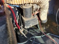
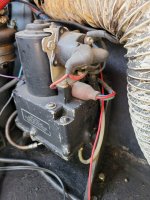
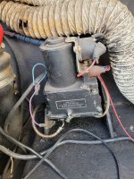
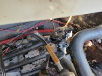
That is a Prestolite pump. I did notice the shift plate lever has 'ALPHA' cast on it. That is a new style plate, and were never designed to have a reverse lock valve on them.
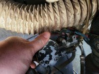
Here's how the valve would have been mounted originally.
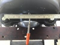
View attachment 339484
Notice the shape of the lever that's designed to be mounted ON the valve. As the control cable pushes the lever to reverse the valve closes, and hydraulic fluid can't flow, stopping the drive from 'kicking up'. It also trips a switch (not visible in this picture) that stops the UP circuit being run while in reverse.
Next time you're out on the water, open the throttle in reverse and see if the drive does kick up. If it doesn't, someone has replaced the original Presolite pump (without internal reverse locking) to one with.
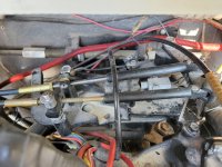
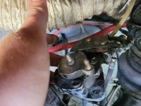
I'd also be interested if you could post a photo of the gimbal housing and drive, and the inner transom plate, viewing the engine flywheel cover and the mountings. Also, could you measure the mounting bolts centre to centre? I have a theory on how you could have a later MC1 (about 1975 to 1982) inner transom plate and an 'Alpha One' gimbal housing (1983+)... That way you'd be able to use a Ford engine (with the wider mounts) and a later (1983+) gimbal housing.
Chris........


 No, they aren't.