What's the trick!?

Blutwtr

Cadet
Joined
Sep 1, 2019
Messages
18
I have a 2003 Merc 150XL SWB. I bought it my boat. Other than some expected wear it has run VERY well. I got an overheat alarm and figured it was the water pump. Ordered one, installed and ready to put lower unit back on. Now the unit will not slide back on. When I removed the LU I had the shifter in forward (saw that on a forum). The drive shaft and water tube are lined up as are all studs and alignment pins. I have moved the shift arm from forward, to N to reverse and have rotated the "shift pin" as well and still no luck. I get about 1/2" and no more. The LU did go on one time but the shift lever (on the motor--cable disconnected) wouldn't budge so I dropped it back off. Now I am stuck at the 1/2" gap.

What am I missing????

All help appreciated.
 

jimmbo

Supreme Mariner
Joined
May 24, 2004
Messages
13,652
You probably need to rotate the Flywheel a bit to line up the splines. You should grease the splines lightly, but do not put any grease on the end of the driveshaft.
 

Blutwtr

Cadet
Joined
Sep 1, 2019
Messages
18
That's just it. The drive shaft went in the first time. I cleaned the splines and put a light layer of never-seize on them. In my mind the shift pin is in the wrong position and it's not lining up as well. Could this be part of the issue?
 

jimmbo

Supreme Mariner
Joined
May 24, 2004
Messages
13,652
Everything has to line up, Shift Shaft, Drive Shaft, Water Pipe to water pump, Studs on Gear Case. The Shift Shafts is splined in a way that they only fit together one way. Examine them prior to an assembly attempt.
 

Blutwtr

Cadet
Joined
Sep 1, 2019
Messages
18
Thanks. I kind of figure that the shift shaft and pin have to go an exact way. Didn't know if there is a "trick/secret" for the proper alignment.
 

Dukedog

Captain
Joined
Oct 6, 2009
Messages
3,439
tha shift shaft not aligning will not keep tha gearcase from going up all tha way.. it will just push tha shift shaft up.. with a flash light look up in tha down housing at tha crank.. you are looking for something laying across tha opening at tha crank.. there is what most call a seal in tha bottom of tha crank that will sometimes pull out when tha gearcase is pulled.. it falls down and will block tha driveshaft from entering tha crank... may or may not be your problem.. jus take a peek..
 

Blutwtr

Cadet
Joined
Sep 1, 2019
Messages
18
Thanks. I will check for that as well. It is weird that it went on the one time and now stops about 1/2" short so that would point to something in the way.
 

jimmbo

Supreme Mariner
Joined
May 24, 2004
Messages
13,652
When you applied the Never Cease, you didn't put any on then end of the shaft? Have you applied a Silicone Lube, or Dish Soap to the Grommet on the Water Pump, to make it easier for the water tube to slide in?

Is there a chance you lifted the shift shaft in the gearcase? On a lot of Merc gearcases, doing so will disengage the shaft from the shift cam, allowing the cam to move and preventing the shaft from reengaging. There were changes made to the shift mechanism, where that changed, but I don't know if you engine uses the old system or newer system
 
Last edited:

Blutwtr

Cadet
Joined
Sep 1, 2019
Messages
18
I only applied Never Seize to the splines and yes there was silicon on the water pump seal for the tube.

As far as the shift shaft, I do think I lifted it. It sits flush and only turns. It doesn't seem to have the ability to lift up but then again I may be misunderstanding exactly what you mean.
 

Texasmark

Supreme Mariner
Joined
Dec 20, 2005
Messages
14,780
I only applied Never Seize to the splines and yes there was silicon on the water pump seal for the tube.

As far as the shift shaft, I do think I lifted it. It sits flush and only turns. It doesn't seem to have the ability to lift up but then again I may be misunderstanding exactly what you mean.

The shift shaft in the lower unit is nothing more than a ⅜" steel rod, splined on both ends. The LU casting has a pair of parallel, horizontal plates cast into the LU with a hole drilled vertically through the plates. The shifter cam slides in from the rear and the shaft is pushed down through the cam and extends on down into the lower casting plate, locking the cam in place.......but not locking the position of the shaft.

The cam and interface with the shift shaft are submerged in LU oil. The upper end is exposed to the elements. Easy to see that in separating the LU from the mid section, the linkage would tend to favor removal at the cam rather than at the intended spot, external to the LU.

I have read on this site where folks were able to peer down in the hole and move the cam such that the shifter shaft stub could be reinserted without having to disassemble the LU go get at the cam to reinsert the shaft. Seems like "Black Magic" to me as the cam follower spring in the prop shaft would make that all but impossible...but that's just an opinion.
 

Blutwtr

Cadet
Joined
Sep 1, 2019
Messages
18
Thanks for all of the info but I have to say you have my head swimming with it. I need to get a picture and share but I'm at work ATM so it will have to wait.

On my motor the shift linkage from the upper unit (shift shaft) is splined on the inside. On the LU there is a splined rod that is welded to a round plate. This splined shaft only rotates on a horizontal plane. From what I can tell is that when the controls are moved it causes the shift linkage to translate into a rotational force vs. a vertical motion. The rotation causes the shaft in the LU to turn either clockwise or counter clockwise. What happens in the actual LU inside the case is beyond me as I can't see (obviously).

All of this may be exactly what you describe however. If I rotate the LU shaft the prop engages. If I rotate the opposite way the prop free spins.

If my description is totally different from what you've seen is it possible the 2003 was an oddball design?
 

Blutwtr

Cadet
Joined
Sep 1, 2019
Messages
18
Here are a couple of pics.
 

Attachments

  • photo320465.jpg
    photo320465.jpg
    128.2 KB · Views: 1
  • photo320466.jpg
    photo320466.jpg
    106.1 KB · Views: 1

Texasmark

Supreme Mariner
Joined
Dec 20, 2005
Messages
14,780
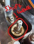
First off the vertical DRIVE shaft has a pinion gear on the bottom end that simultaneously connects to F and R gears thus causing them to rotate in opposite directions and do so as long as the crankshaft is rotating. The shifter mechanism uses a sliding "Clutch Dog", mounted on and locked to (the rotation of) the PROP shaft to select which gear will be selected, operated by the cam attached to the splined shifter rod you circled.

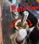
In Neutral, the Dog connects the PROP shaft to neither the rear of F gear nor the front of R gear so the prop shaft is free wheeling. To shift gears, the Dog is forced into one or the other of the engagement gears. There is a spring loaded "CAM Follower" (a hollow, round nosed, spring loaded, bullet) that is moved back and forth along the PROP shaft, executing the F or R gear engagement as a function of the position of the shifter CAM (a flat plate with a splined hole for control and 3 dug-out areas different distances from the pivot point for controlling the CAM follower mentioned above); rotation is horizontal as you mentioned.

F is the first detent in the cam and is the closest to the splined shaft (pivot point) and puts the least amount of pressure on the "cam follower" allowing the spring to relax and allow the clutch dog to lock into the rear of the F gear locking it to the PROP shaft. This is evidenced by CCW rotation of the propeller, looking from the rear and watching the drive shaft rotate. CW rotation in F is an over run clutch which allows the prop to turn with out the drive shaft turning with a clicking noise while being rotated and a slight in-out movement of the prop shaft to the LU housing.

Rotating that shifter shaft to the center position is N and the cam detent for that is slightly farther away from the pivot point causing more pressure to be applied to the spring loaded CAM follower causing the "Clutch Dog" to move into it's central position along the PROP shaft and in not touching either F or R gears the PROP shaft is free to free wheel.

Continuing to rotate the shifter shaft, you rotate the cam to the farthest position from the pivot point putting maximum pressure on the CAM follower spring and forcing the Clutch Dog into the front of R gear thus connecting it to the PROP shaft and Reverse operation. Unlike F gear, the connection between the Clutch Dog and R gear is cogs and sockets with vertical sides. SLIGHT pressure is applied to the shifter shaft as the prop is rotated. Engagement will come when a cog and socket line up and then the shifter shaft can continue it's rotation to full engagement......any time the engine isn't running, the prop must be rotated by hand while attempting to engage R gear to prevent damage to the shifting linkages....per the manual.
Once in R gear, rotating the prop in either direction will cause movement of the DRIVE shaft in a corresponding direction with no slop.

Does that help? Want more, ask.
 

Blutwtr

Cadet
Joined
Sep 1, 2019
Messages
18
LOL, holy crap. That is a lot of techno speak above my paygrade (obviously). I do appreciate the detailed explanation though. I will try again today to get everything to line up and engage properly while being sure that the prop etc. is in the proper position in regards to the shift rod from the UU and the control cables etc.
 

Texasmark

Supreme Mariner
Joined
Dec 20, 2005
Messages
14,780
If you can't get it lined up the next thing is to pull the Prop shaft. Not all that hard once you set your mind to it. With it out and the F gear, thrust bearing and shims (if any) removed, you can get to the cam plate to reposition it and stab the shaft...will help with that if needed.
 
Top