Wiring!

rpastor

Seaman Apprentice
Joined
May 21, 2010
Messages
43
Greetings,

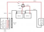
I am finished painting my project boat and am going to start wiring. I have attached a wiring diagram that I have drawn up. Does this look okay to you experts?

My other question is this: I have a Perko 8501DP switch. The documentation says that it is okay to switch between 1, 2, or All, just NEVER switch to OFF. My plan is to start on Batt 1, switch to my house battery while running out/in. I know that an ACR would do this automatically, but I have a low amperage alternator and don't want to charge both batteries at the same time. I trailer the boat so the batteries get a trickle/maintenance charge once I get home. My concern is about my electronics. Is there any danger in having my house circuits and starter circuit on the same bus? The house circuit is protected by a 50 amp fuse.

The fuse panel is 13 feet from the positive bus and I am running 4 gauge wire to both the fuse panel and the negative bus. The other wiring is going to depend on the circuit, minimum being 14 gauge. I will be running either 4 gauge or 2 gauge to the engine.

I am either going to run the Bilge and baitwell through the panel or on separate circuits since they are closer to the battery switch.

Is my plan sound?
Wiring.jpg
 

sw33ttooth

Chief Petty Officer
Joined
Apr 24, 2011
Messages
498
Re: Wiring!

looks fine to me cept i would run bilge and livewell to fuse pannel and if they have an alternate wire i would get a 3 way switch for the dash and wire it in. the alternate wire, was ment to be set up as: on, off, auto. auto meaning like your bilge, would pump out any water that got in there after a certain level. for the livewell i've seen some boats that when you flip the auto the live will well fill with water for a minuite every 5 or 10 minuites to keep water freash.

by the way why can't you switch your main to off? i always turn mine off when i pull it out incase i left a light on or the stereo.
 

rpastor

Seaman Apprentice
Joined
May 21, 2010
Messages
43
Re: Wiring!

Turning it off while the engine is running will fry my alternator.

Let me see if I have it straight. Use two three-way switches, one for the bilge pumps and one for the bait well. When either is switched to on, they will run continuously. When switched to auto, the bilge pumps will run if the either float switch is closed. If switched to auto, the bai twell pump, depending on brand, will recycle the water on a schedule.

I was thinking about maybe doing that but, since both the bilge pumps and bait well are aft, I was also toying with the idea of running a fused, switched line to them directly from the positive bus near the battery switch. Is there an advantage to either?

The boat is going to be used for diving or fishing, generally not both, so I'll be removing the bait well to make room for tanks when diving. I plan on putting a disconnect on that side of the boat. Any ideas?
 

jhebert

Ensign
Joined
Jul 24, 2005
Messages
903
Re: Wiring!

I have attached a wiring diagram that I have drawn up. Does this look okay to you experts?

The schematic diagram of your primary power distribution shows a proper installation, except for one minor variation. You have not created a negative bus common point, but instead have daisy-chained the battery negative terminals. This is very commonly done in small boats. I do not see it as a problem. I confess that my boat is wired in the same way.

The typical OFF-1-BOTH-2 battery switch is arranged with contacts which have a make-before-break arrangement, so you can safely move the switch from 1 to BOTH or from BOTH to 2 (or vice versa) without interrupting the power distribution at the COMMON terminal. In this way you will not harm your alternator during the switching. You must take caution NOT to move move the switch through the OFF position when the engine is running, as this is when damage to the alternator can occur.

The arrangement you have shown for primary power distribution is very common on small boats with single engines and two batteries. I would resist adopting suggestions that you make if more complicated. The more complex the system of switches, sources, and loads, the more likely there will be problems operating the system.
 

Don S

Honorary Moderator Emeritus
Joined
Aug 31, 2004
Messages
62,321
Re: Wiring!

My suggestions.
1. Remove the buss bar just above the battery switch. There is plenty of room on the battery switch for 2 cables, and it's less connections to go bad.
2. 4ga. cable to the helm is way over kill. 8 ga. would be max size needed with a 30A breaker. With all your accessories on, including the bilge pump, blower, live well, you will not be near 30 amps. I used 8 ga and had a cabin heater, refrigerator, and water pump as well.
3. Hook your manual bilge pump to the helm switch, but hook up an automatic float switch for the pump. And wire it with a fuse to the house battery terminal on the battery switch (for neatness). Then the pump will come on anytime water gets in the bilge even if the battery switch is off. Keeps the bilge dry, even if you are in the driveway and forgot to remove the drain plug.

I am either going to run the Bilge and baitwell through the panel or on separate circuits since they are closer to the battery switch.

Keep the switches at the helm, seperate 14 ga hot wires to the bilge pump and livewell will be fine, just add a small ground buss near the battery for grounds for the bilge and livewell pumps.
 

jhebert

Ensign
Joined
Jul 24, 2005
Messages
903
Re: Wiring!

My suggestions.
1. Remove the [bus] bar just above the battery switch. There is plenty of room on the battery switch for 2 cables, and it's less connections to go bad.

In electrical wiring practices, particularly in connections involving high current, there is a general standard that only one terminal should be fastened under a terminal post. Attaching multiple wires with multiple terminals to a single wiring post is considered bad practice. While it is often done, I would not recommend it as being a better alternative. A binding post is more likely to develop a loose connection if there is more than one terminal attached to it. Use of a bus bar with individual binding posts is a better solution.
 

rpastor

Seaman Apprentice
Joined
May 21, 2010
Messages
43
Re: Wiring!

Is there any danger to my electronics wiring it this way?
 

jhebert

Ensign
Joined
Jul 24, 2005
Messages
903
Re: Wiring!

Is there any danger to my electronics [if the boat is wired in the] way [that was shown the original diagram linked above]?

Your boat's electronics will be powered by the same battery you will use for engine starting. During engine starting it is common for the battery terminal voltage to sag due to the load of the engine cranking motor. When the battery terminal voltage sags it could fall below the threshold voltage for the electronic devices to operate properly. One often sees that some electronic devices will restart themselves after engine cranking due to such a sag in voltage. Whether or not you will experience this problem depends on many factors, including the strength of the battery, its state of charge, the nature of the motor being started, and how long it has to be cranked over to start.
 

rpastor

Seaman Apprentice
Joined
May 21, 2010
Messages
43
Re: Wiring!

Well, since the only thing the starting battery has to do is start and I will be keeping it charged, I'll have to take my chances. The only way I can see around this is to use an ACR, which I was hoping to avoid.

It's a very old 175 hp motor, in better shape than a lot of newer motors, and only has to crank briefly to start. In fact, I have been able to start it with a pull rope. The starter draws 200 amps peak. The alternator only puts out 10 amps which is why I am avoiding the ACR.
 

Don S

Honorary Moderator Emeritus
Joined
Aug 31, 2004
Messages
62,321
Re: Wiring!

In electrical wiring practices, particularly in connections involving high current, there is a general standard that only one terminal should be fastened under a terminal post. .

Putting the starter cable and the power cable to the helm on the same terminal on the battery switch is very common. Boat manufacturers do this all the time.
This is not a constant high amperage condition. The starter will pull 3-400 amps for a few seconds, then there is nothing more that helm power coming from the switch, and that is NOT considered high amperage.

This not high amperage/high voltage systems.
 

rpastor

Seaman Apprentice
Joined
May 21, 2010
Messages
43
Re: Wiring!

Thanks, Don,

Are you sure 8 gauge and a 30 amp fuse is all I need running to the helm? The sum of the max amperage of my house circuits is 60 amps. Since the run is 10' (20' round trip), the table I'm using recommends 4 gauge (borderline 2 gauge). Wouldn't I need to fuse the house circuit with a 60 to protect that wire?

I would probably turn down the audio prior to transmitting on VHF and rarely crank it all the way up, saving 5 - 10 amps. The bilge and bait well come on intermittently, but could both come on at the same time. It could happen, therefore, although unlikelikely, that everything will be powered up at the same time.

Bob
 

rpastor

Seaman Apprentice
Joined
May 21, 2010
Messages
43
Re: Wiring!

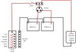
wiring 2.jpgHere's my new schematic. How does this look?

Bob
 
Last edited:

Don S

Honorary Moderator Emeritus
Joined
Aug 31, 2004
Messages
62,321
Re: Wiring!

Are you sure 8 gauge and a 30 amp fuse is all I need running to the helm?

Yes, unless you have some huge pumps, a normal size bilge pump for your boat would pull around 3 A when running, and probably about the same for the livewell. For the VHF, unless transmitting, it will never pull more than 1. Nav lights maybe 3. Audio, I doubt will be more than 2 very often. GPS and fish finder same thing, even with a huge color display, they don't pull more than 2 each.
That makes 12 or 13 amps if you run everything all the time.
Sitting there fishing with the baitwell pump on and the stereo & FF/GPS will be 5 or 6 amps. Hardly worth the expense of 4 ga. cable and 60A fuse.
 

rpastor

Seaman Apprentice
Joined
May 21, 2010
Messages
43
Re: Wiring!

Your right, I was looking at 15 watts for the GPS. It has a 5 amp fuse. I am basing my current draw on either the specs or the inline fuse. I also want no more than a 3% voltage drop. It is a 17' wire run from the battery switch to the helm.

I have reworked everything. My audio system draws 5 amps but I am allowing 10 A in case I add an amplifier. Bilge and baitwell draw 4.8 A each. I am putting Nav lights and horn on the same circuit for 5 A. GPS/FF draws 5 A. I know that the VHF doesn't draw much unless transmitting which is 5 A. That still makes 30 A. Since I want no more than a 3% voltage drop over a 34' out and return circuit, AWG 4 is the recommended gauge. Even if I only draw 20 A, it would still call for AWG 6. Since there is only $0.18/ft difference between 4 and 6, the extra cost is not really a concern. I always go one step above code in all my electrical work, if I can.

Bob
 
Top