Step By Step Impeller Change

Status
Not open for further replies.

J2theGriff

Cadet
Joined
Mar 23, 2009
Messages
6
Re: Step By Step Impeller Change

How does this procedure differ on a '93 Force 90hp?I am about ot attempt an impeller change because of the age and the motor has sat for awhile...it runs great but only spits a small amout of water. I will also be doing a lower end seal kit..but I'll leave that to the pros. Thanks for any help!!
 

brose

Cadet
Joined
Oct 20, 2008
Messages
20
Re: Step By Step Impeller Change

Hey Frank, Thanks for the info on the impeller swap, I bought a manual for the Force covering all years from 84 to 99 and it was pretty vague on a couple of steps. You rock man!!!!!!!!
 

ctodorov

Recruit
Joined
Apr 25, 2009
Messages
1
Re: Step By Step Impeller Change

Hey you, I am from Bulgaria and have a boat with an engine FORCE 125 (1251x8c), can anyone tell me how to do centering of carburettors? THANK YOU
c-todorov@hotmail.com
 

sreed382

Recruit
Joined
May 26, 2009
Messages
5
Re: Step By Step Impeller Change

Well at least I know where my drain plug is.Seloc was of no help,varey little anyways.This site is like manna from heaven.
 

sruman

Cadet
Joined
Jun 6, 2009
Messages
24
Re: Step By Step Impeller Change

Just curious, will water circulate prior to the thermostat opening? I have an 86/125 Force, and I'm having similar problems. I'm afraid of letting the engine idle over 20 seconds, for I don't want to damage the engine. During this time, I don't have water coming out of the two water outlet holes. Do I need to let the thermostat open, or should water being flowing regardless if the engine is hot enough to open the thermostat?
 

harkawy

Petty Officer 2nd Class
Joined
Jun 27, 2005
Messages
155
Re: Step By Step Impeller Change

My 1995/6 Force pumps water from the moment it starts. I believe that the thermostat prevents the water from the water jacket until it opens, but doesn't prevent it from the telltail.
 

drydoc

Recruit
Joined
Jul 19, 2009
Messages
1
Re: Step By Step Impeller Change

I have a 85 hp force by u.s. marine and was told the impeller is plugged. does this sound like a common problem and how do i go about fixxing it?
 

william crosby

Recruit
Joined
Aug 27, 2009
Messages
2
Re: Step By Step Impeller Change

These instructions will apply to all three and four cylinder Chrysler one piece lower units, all years, up to all three and four cylinder Force units to 1989. They are all the same design. After 1989, Mercury started to make changes and while the lower units were essentially similar, minor variations were present until Merc completely changed to a Merc midleg and lower unit.

Changing the water pump impeller is easier to do with the engine tilted up.

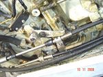
Below the engine mounting clamps (actually, below the lower engine pivot mount--a plate with 4 bolts holding it) you will see a cylindical shift linkage connector. It will be held with a small pin through it and a smaller cotter pin through the small pin. Pull out the cotter and slip out the pin. The shift linkage is now disconnected.

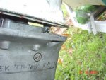
Now, after noting and marking its position, (because it acts as a trim tab) remove the exhaust snout. It will be held on with a flattened 5/8 inch head bolt just above the propeller. Inside the back of the snout will be either a 1/2 inch hex head or a 3/8 inch socket head cap screw. This holds the back of the snout on.

Up inside the now exposed exhaust cavity you will find the 7th hidden mounting bolt. It will be a 1/2 inch hex head unless it was stripped and re tapped to 3/8 bolt with a 9/16 hex head. Remove it.

Now remove the six (1/2 inch hex head) exposed mounting bolts under the cavitation plate. The lower unit may just slide right down, or it may take a little persuasion with a rubber mallet. The black rubber crankshaft seal will probably come off the top of the drive shaft as well as the steel collar. If they stay up inside the midleg, lower the engine and they should just fall out. If not, tap and jiggle a bit. When you go to replace the lower unit, the collar goes on with the groove facing up and the rubber seal goes on with the beveled end up.

Now you will see the water pump held on by four 7/16 hex head bolts. Remove them--they may be corroded in and will in all probability fight you. Be careful, they are 1/4 inch bolts and are easy to snap. If they are real tight, try rocking them with the wrench, increasing the turning out by about 1/16 - 1/8 turn each rock or twist. Sometimes this keeps them from snapping. Use a green Skotch brite pad to clean the drive shaft. If corrosion is heavy, you may need to use medium sandpaper. Lift off the pump housing and the impeller may or may not come with it. Do not lose the drive key--it is a special one and costs 8 bucks. Check the inside of the housing for heavy corrosion, deep pitting, deep gouges, or excessive wear. Replace if any of these are present. Light scratches and scuffing in the walls are normal and acceptable. (Clymers doesn't tell you this)

You will have previously purchased both an impeller and a gasket that goes under the stainless steel plate below the pump housing. Lift off this plate and the gasket will most likely be damaged. scrape off the old gasket and check the condition of the lower plate (housing). If the passage walls are corroded to the point where the new gasket will not seal them, they will bypass water from the outlet to the inlet and pump efficiency will be reduced. So: if they are well corroded, either repair them with a good epoxy or buy a new lower plate. (Clymers does not tell you this) This plate is kinda pricey because it carries the drive shaft seal, so it is worth a try to repair it if it needs it. (Or this)

Install the new gasket and stainless plate. Install the key and impeller on the shaft. Lubricate the pump housing with dish soap and push it down over the impeller with a counter-clockwise twisting motion. The impeller is larger than the pump housing and the turning sets the impeller blades in the correct direction as they enter the pump housing. (They don't tell you that either.) Now, put anti seize on the bolts so they come out easier next time and hand tighten. Tight--but you don't need to kill them. Too tight and you run the risk of warping the pump housing or stripping the bolt holes. The bolts are going into aluminum.

The lower unit is heavy so if you are not in good physical condition, have someone help to hold the unit while removing and re-installing. They can also help by turning the flywheel to line up the splines. Coat the splines with a light coating of anti-seize--too much is no good; it may pre-load the shaft when assembled in the crank. I also like to coat the whole shaft with anti-seize to help prevent corrosion. I rub it in with a paper towel to assure good adhesion. When re-installing the lower unit, you must feel around to get the drive shaft into the crankshaft splines. Be sure that the brass water tube is seated in the plastic collar on the pump. Then just put everything back together with anti-seize on all bolts. Remember to reconnect the shift rod.
hi do you know if this is the same way to replace the impeller in a 1990 120 force inboard with l drive thanks
 

bowman33

Recruit
Joined
Aug 24, 2009
Messages
4
Re: Step By Step Impeller Change

Uh! Yeah! I could, but I wanted to keep the answer short, and my wife was bugging me to get off the computer.
HELLO FANK. I OWN A 40 FORCE OUTBOARD. MY MANUAL SAYS 1995 BUT THE FLWWHEEL HAS 1996 STAMPED ON IT.. I NEED TO CHANGE THE IMPELLER ARE THE INSTRUCTIONS THE SAME AS ABOVE? HOW DO I NO THE YEAR ? I NEED TO LOOK INTO THE IMPEELER AND A STATOR FOR THIS.. THANKS FOR YOUR RPLY
KEVIN
 

Llunker

Petty Officer 2nd Class
Joined
Sep 17, 2009
Messages
106
Re: Step By Step Impeller Change

Just thought I would add to this post for a 1997 120hp Force outboard --straight from my seloc manuel.

# Disconnect the spark plug leads.

# Shift the unit into forward gear.

# Remove the fasteners holding the lower unit in place. 4 total

# Carefully pull the lower unit down to remove.

# Support the unit in a lower unit holder or a vise.

# Remove the fasteners holding the water pump housing in place.

# Remove the housing and impeller up and slide off the driveshaft.

# Remove the impeller wear plate and gaskets.

To install:

A brush on gasket sealer would be recommended in saltwater applications or when the housings are in marginal condition.

# Install the water pump plate and gasket(s).

# Place the impeller key into the slot on the driveshaft.

# Slide the water pump impeller down the driveshaft.

# Align the slot in the water pump impeller with the key and slide down into place.

# Lower the water pump housing down the driveshaft.

# With a clockwise twisting motion of the driveshaft push the pump housing over the impeller.

# Lubricate and install the fasteners that hold the pump housing in place.

# Lubricate the driveshaft splines on the sides only. Grease on the top of the shaft could cause it not to be able to fully seat into the crankshaft.

# Lift the lower unit from the holder or vise.

# Align the driveshaft with the tube or cavity and push the lower unit up into the mid housing.

It may be necessary to rotate the driveshaft or flywheel to align the driveshaft splines.

# Be certain that the water tube is aligned with the water pump outlet and shift splines are aligned with the shift connection then slide the unit into place.

# Move the lower unit up flush with the mid housing.

# Install the attaching hardware.

# Attach the spark plug leads to the spark plugs.

# Supply the engine with an appropriate water supply.

# Start the engine and test the water pump output.

If water does not appear to be flowing through the engine immediately shut the engine off. There could be a water supply problem or a misalignment in the water tube.
 

Stachi

Lieutenant Commander
Joined
Jul 14, 2009
Messages
1,671
Re: Step By Step Impeller Change

I beg to differ with this step , removing the exhaust snout......I have used a 1/4" drive 1/2" socket with an 8 inch , 1/4 " drive extension , with a universal joint between socket and extension ,I was able to remove the 7th bolt without removing the exhaust snout.... much easier than it sounds and saves a few steps,....every bolt you try to remove could result in a headache to repair if it breaks off...especially on older engines... the rest of your R+R is on target .... tight lines all !

also , when re-installing lower unit , you can turn the prop to align the driveshaft splines, same idea as turning the engine , but much easier to do alone...
 

BillE

Recruit
Joined
Nov 12, 2009
Messages
1
Re: Step By Step Impeller Change

Just bought a 1988 Blue Fin w/ Force 50 hp
started purty easy, but no pee stream.
Is there instructions for changing the impellar for this model available?
 
Last edited:

wickware

Lieutenant
Joined
Jun 20, 2009
Messages
1,286
Re: Step By Step Impeller Change

I followed the instructions above and changed mine, first time, take your time, biggest problem will be making sure you keep your forward/Neu/reverse/. correctly lined up. Take your time, if I did it anybody can,

SeaForce

1. If the gear-shift-rod is disconnected at the cotter pin vs adjusting linkage (on the 1970 35HP Chrysler), readjusting the forward, neutral and reverse should not be necessary, Right?

2. It was tight but I was able to disconnect in a small leg opening after disconnecting some linkage at the motor (attached).

3. Was this the best option or was there another way to get to the cotter pin?

4. Maintaining the boat, motor, trailer and etc (off-season) and working firewood over the years has always seemed strange and ?old now?, But Fun!

Thanks for comments in advance.

JOW
 

Attachments

  • 70 Chrysler 35 HP Water Pump Checked Last In 1985.JPG
    70 Chrysler 35 HP Water Pump Checked Last In 1985.JPG
    86.7 KB · Views: 1
  • 70 Chrysler 35 HP Water Pump Checked Last In 1985 3.JPG
    70 Chrysler 35 HP Water Pump Checked Last In 1985 3.JPG
    63.9 KB · Views: 1

wickware

Lieutenant
Joined
Jun 20, 2009
Messages
1,286
Re: Step By Step Impeller Change

Quote:
Originally Posted by SeaForce1962 (from post above)
I followed the instructions above and changed mine, first time, take your time, biggest problem will be making sure you keep your forward/Neu/reverse/. correctly lined up. Take your time, if I did it anybody can,

SeaForce


My Questions/Concerns:

1. If the gear-shift-rod is disconnected at the cotter pin vs adjusting linkage (on the 1970 35HP Chrysler), readjusting the forward, neutral and reverse should not be necessary, Right?

2. It was tight but I was able to disconnect in a small leg opening after disconnecting some linkage at the motor (attached).

3. Was this the best option or was there another way to get to the cotter pin?

4. Maintaining the boat, motor, trailer and etc (off-season) and working firewood over the years has always seemed strange and ?old now?, But Fun!

Thanks for comments in advance.

JOW
 

Attachments

  • 70 Chrysler 35 HP Water Pump Checked Last In 1985.JPG
    70 Chrysler 35 HP Water Pump Checked Last In 1985.JPG
    86.7 KB · Views: 1
  • 70 Chrysler 35 HP Water Pump Checked Last In 1985 3.JPG
    70 Chrysler 35 HP Water Pump Checked Last In 1985 3.JPG
    63.9 KB · Views: 1

chillidogsrus

Recruit
Joined
Mar 7, 2010
Messages
1
Re: Step By Step Impeller Change

I did it last night and Frank was 100% to the T on everything. Thanks Frank.. 1989 Force 125 O/B on a 1989 Bayliner Capri
 

gabourie

Recruit
Joined
Mar 31, 2010
Messages
2
Re: Step By Step Impeller Change

Cheers,

I have a 1973 Chrysler 9.9hp Model: 92BE 1243. The waterpump impeller needs replacing. The local shops I've contacted do not know where I can find an impeller for this engine, can anybody help me out and direct me to a shop who may have this impeller?

Thank you
 

Banditz

Petty Officer 2nd Class
Joined
Apr 21, 2010
Messages
168
Re: Step By Step Impeller Change

Wow,,,tons of questions, barely any answers.

Not an expert on this guys, but I may be able to help out.


50hp force engines do not have stock pee holes. the water instead kinda spurts out the back. May take a few seconds but will get stronger in the water than from a hose.

From what I gather, this tutorial is basically a guide that will get you through your impeller install. It's kinda a general guide if I may say so frank?
From the outboards i have worked on, and the one alpha inboard i had, the guide is a how to that may or may not apply to all outboards and inboards, but frankly its very close.

If you need a part, just google, yahoo search or otherwise find a parts diagram for your engine and once found, get the part number off the part you need. Then google that part number and there you have it! this site also seems to have alot of stuff too so....

And again, if your asking if this applies to your particular install, the best and sure fire way to find out.....tear yours apart and take plenty of pics. Then you will know when your finding new parts.

Also...black PVC seems to hold up pretty damn good for a gasket maker.
IMO of course.

Oh yeah, and yep...needs to be in first gear so you have more room to remove the forward/reverse lever cotter pin. Otherwise, you will have a tight fit looking in there to find it!
 
Status
Not open for further replies.
Top