2xMercruiserOwner
Cadet
- Joined
- Sep 13, 2017
- Messages
- 6
Recently acquired this boat... has dual helm stations.
Both my engines were running and I decided to do a tune up to each as it appeared they had really old parts and starboard started to have the coil arching while running. I first did my starboard and found 2 wires with torn boots at the plugs. Started right back up after doing cap, rotor, wires, plugs and compression test with bump starter.
Now my port engine is a crank no start after doing the same. I am seeing that while cranking that I do not get spark signals to my cap from coil, nor to the plug wires. I swapped coils and same... both are good as both were used on other engine to start the other engine. While the spark plug light tester was in between the coil and dist cap, when key is switched on, I do see one quick light on it. Cranking the engine does not show anymore light flashes. I placed the test light in between the cap and one wire out and I get the same, I get a light flash when key is turned one but no more flashes during cranking.
Best I can gather is that I have power then at coil but maybe it's not grounding as not to pulsate the signal. I have not tested it to say it is 12v.
In doing the service, I replaced the cap, rotor, wires, plugs. I did a compression check by using a bump starter. I forgot to unplug the coil from cap during one bank testing, so had about 40 cranks that way but key was off. In taking off the rotor, I used a heat gun to get it warm as to then pry the rotor off the dist post. I also took of the engines lift eyelet near dist cap to give me more room to pry rotor. I then see a little coolant leaking near there then realized the eyelet bolts secure the intake to block and removing it caused the leak. I sanded the rotor post and other metal in before putting new rotor on as surfaces are older and had a like rust build up. I vacuumed the area out. I can't think of anything else I would have done during the service to cause the no spark afterwards...
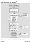
I am a near novice when it comes to electronics... so I am not exactly sure of the best grounding locations to get a reading on the coil for a 12v check. I just bought the mercruiser service manual #9 which has a high level only outline of trouble shooting this but no detail on the testing of say the engine wiring harness, ignition brains, safety shut off logic, etc.
Would someone kindly provide advice on this thunderbolt iv system?
Thanks in advance !
Last edited:


